Posted on

K&D Kendrick and Davis Staking Tool Inverto Patent

Publication number US923495 A
Publication type Grant
Publication date Jun 1, 1909
Filing date Aug 21, 1908
Priority date Aug 21, 1908
Inventors Frank R Cunningham
Original Assignee Kendrick & Davis
Classifications (1)
External Links: USPTOUSPTO AssignmentEspacenet

DESCRIPTION  (OCR text may contain errors)
F. CUNNINGHAM.
STAKING TOOL. APPLICATION FILED Aug 21 1908.
Patented June 1, 1909.
WASHINGTON, D.C.
UNITED STATES PATENT OFFICE.
FRANK R. CUNNINGHAM, OF MEDFORD, MASSACHUSETTS,
ASSIGNOR TO KENDRICK & DAVIS, OF LEBANON, NEW HAMPSHIRE.
STAKING-TOOL.

Specification of Letters Patent.
Patented June 1, 1909.
Application filed August 21, 1908. Serial No. 149,725.

To all whom it may concern:

Be it known that I, FRANK CUNNINGHAM, of Medford, in the county of Middlesex and State of Massachusetts, have invented certain new and useful Improvements in Staking-Tools, of which the following is a specification.

This invention relates to staking tools for jewelers and watch-makers work, and has relation to a clamp by which the punches, centering tools or other operating tools used in this sort of apparatus may be held unyielding in any position, and may be readily released.

The invention consists in spring clamps and a holder therefore, which are associated with the rest of the staking tool so that they may press yieldingly upon and grasp the shank of the operating tool, but may be released by a simple rotary movement of the holder.

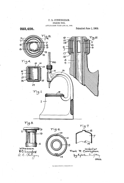
Of the accompanying drawings ,Figure 1 represents an elevation of a staking tool having my improvement applied thereto.

Fig. 2 represents a vertical section through the head of the staking tool and the attachment. Fig. 3 represents a horizontal section of the staking tool head and of the attachment constituting my invention. Fig. 4 represents a sectional view taken on line 44 of Fig. 3. Fig. 5 represents an elevation of the upper part of the tube which is set into the head of the staking tool and upon which the attachment constituting my invention is mounted. Fig. 6 represents a plan view of the bottom of the clamp holder forming part of my invention. Fig. 7 represents a perspective view of one end of one of the spring clamps.

The same reference characters indicate the same parts in all the figures.

A staking tool is shown in Fig. 1. and consists as usual of the base 1 having a die plate 2 and a curved neck 3 with a head 4 which overhangs the die plate. This head, as appears most clearly in Fig. 2, is bored vertically, and contains a tube 5 having along latitudinal bore or passage through which the punch centering member or other operating tool used in connection with a staking tool, is passed. My invention has to do entirely with a device by which the operating tool may be retained against displacement through the passage by gravity, while permitting such ,tool to be moved by the application of a slightly greater force, and with the means by which the device may be rendered inoperative by a single slight movement.

 The device constituting the invention consists of a clamp holder 6 in the form of a sleeve, and spring clamps 7 and 8 contained in such sleeve. The sleeve is journaled upon a portion of the tube 5 which projects above the head 4 and is contained between the upper end of this head and a flange 9 on the tube. The clamps are in the form of spirally curved flat springs which are contained within the sleeve 6, the interior diameter of which is sufficiently greater than the tube 9 to contain the springs and permit flexibility.

At or near the upper end of the clamp holder is an internal flange 10, the annular surface of which. fits an upper bearing surface 11 of the tube 5, while the other end of the sleeve is recessed to receive an annular plate 12. In the angle between the side walls and flange of the sleeve is a groove 13, and in the plate 12 near its periphery are notches 14. This groove and these notches are provided to receive lugs 15 and 16 on opposite sides near the outer ends of the springs which form the clamps. In assembling the parts, these springs are placed in the clamp holder 6 with their outer ends lying against the cylindrical walls thereof and their lugs 15 entering the groove 13.

They are adjusted so that the lug 16 of each will enter one of the notches 14 of the plate 12, and the latter plate is then put in place. It is preferably made so that it will fit tightly into the end of the holder 6 and abut against shoulder 17 formed therein.

The inner ends of the springs are straight and parallel with each other, lying on opposite sides of the center of the clamp holder, and when not distorted, located at a distance from one another less than the diameter of the shank of an operating tool. .Then the clamp holder is mounted upon the hearing tube 5 the clamps lie on opposite sides of the latter. They are enabled to make contact with and grasp the shank of the operating tool by reason of the fact that the tube 5 is slabbed off on opposite sides to a depth sufficient to provide openings or slots 18 and 19 which communicate with the internal bore or passage, and are of sufficient length to admit the spring clamps.

When the clamp holder is in the position shown in Fig. 3, the clamps enter the openings 18 and 19 and bear against the shank of the operating tool, grasping the same with a yielding pressure, which is sufficient to hold the operating tool in any position which it may occupy and prevent it from slipping downward against the die plate.

In Fig 1 an operating tool is represented by the punch 20, this figure illustrating how the tool is held up by the spring clamps. Upon rotating the clamp holder 6 slightly in either direction, the ends of the springs which form the clamps abut against the sides of the tube 5 adjacent the openings, and are drawn outward by the wedging action of the same so as to be removed from contact with the tool shank. The operating tool is then free.

Thus the parts of the tube adjacent these openings, or, in other words, the walls of the openings, constitute abutments which, when the clamp holder is in one position, retain the springs out of engagement with the operating tool and, when the holder is in another position, allow the springs to press with a yielding frictional engagement against the tool.

I claim

1. A staking tool having a head provided with a passage through it for admitting an operating tool, a spring friction member supported on said head and arranged to bear normally with a yielding frictional pressure upon such tool, and means for disengaging said friction member from the operating tool.

2. A staking tool having a head provided with a passage through it for admitting an operating tool, a holder mounted movably with respect to said head, a spring friction member carried by said holder, and means constructed to hold said friction member out of contact with such operating tool when said holder is in one position, and to permit said member to bear with a yielding frictional pressure on the tool when the holder is in another position.

3. A staking tool having a head provided with a passage through it for admitting an operating tool, a holder mounted rotarily on said head, a spring carried by said holder and arranged to bear with a yielding frictional pressure against such operating tool, and an abutment located beside such passage in the path traversed by said spring when rotated, whereby rotation of said holder causes the spring to engage said abutment and to be withdrawn thereby from engagement with the operating tool.

4. In a staking tool, a head having a tubular bearing for an operating tool, a holder rotarily mounted on said head, springs carried by said holder arranged to enter slots in the sides of said tubular bearing and press yieldingly against the shank of such operating tool, and adapted to be withdrawn from contact with the tool when the holder is rotated.

5. In a staking tool, ahead, a tube set in said. head having a bore to receive an operating tool and having an opening in its side, a sleeve rotarily mounted on said tube, and a spring held in said sleeve with its end arranged tangentially of the shank of said operating tool, and located so as to enter such opening and press against said shank, being withdrawn from contact therewith when the sleeve is rotated.

6. A staking tool having a head provided with a passage through it for admitting an operating tool, a holder mounted movably with respect to said head, a spring friction device carried by said holder for holding such operating tool with a yielding pressure, and an abutment against which said friction device is brought by movement of said holder and by which said device is Withdrawn from engagement with the operating tool.

7. In a staking tool, a head having a passage to contain an operating tool and provided with a lateral opening affording access to the passage, a sleeve rotatably mounted on said head, and a spring carried by said sleeve arranged to enter said lateral opening and bear yieldingly on the shank of the operating tool to serve as a frictional retainer therefor, said spring being caused to Withdraw from said shank by bearing against an edge of the opening when the sleeve is rotated.
8. In a staking tool, an independent clamp holder, spring clamps carried thereby adapted to grasp the shank of an operating tool yieldingly, and provisions for causing said clamps to release the operating tool While said holder remains in connection with the staking tool.

9. In a staking tool, an independent clamp holder, spring clamps carried thereby adapted to grasp the shank of an operating tool yieldingly, and fixed abutments on the staking tool arranged so as to be engaged by said clamps, when the holder and clamps are moved out of grasping position, and thereby cause withdrawal of the clamps from said shank.

10. A staking tool having a head, a tube et into said head having a bore to receive an operating tool, a clamp holder journaled on a part of said tube, and spring clamps carried by said holder; the tube having openings communicating with its bore in the zone surrounded by the holder into which said clamps extend to grasp the shank of said operating tool when the holder is in one position and from which the clamps are retracted by abutting against the sides of the openings when the holder is turned into a different position.

11. In a staking tool, a clamp holder consisting of a sleeve having an internal flange near one end and an annular plate attached removably to the other end thereof, and spirally coiled springs held at their outer ends between said flange and plate, their inner ends being free and arranged to grasp between them the shank of an operating tool.

12. In a staking tool, a clamp holder connects ends being free and arranged to grasp resisting of a sleeve having an internal flange between them, the shank of an operating tool near one end and an annular plate attached.

In testimony whereof I have affixed my removably to the other end thereof,  said signature, in presence of two witnesses observing the plate having notches, and spirally coiled springs held at their outer ends between, said FRANK CUNNINGHAM’S flange and plate, each spring having a lug returning one of the notches of said plate and 
held thereby against displacement.

Witnesses:

 A. O. RATIGAN.
 C. F. BROWN,

CLASSIFICATIONS
Cooperative Classification G04D3/04
Posted on

K&D Kendrick and Davis Poising-calipers.

Publication number US984354 A
Publication type Grant
Publication date Feb 14, 1911
Filing date Oct 23, 1907
Priority date Oct 23, 1907
Inventors Frank R Cunningham
Original Assignee Kendrick & Davis
Referenced by (3), Classifications (1)
External Links: USPTOUSPTO AssignmentEspacenet

DESCRIPTION  (OCR text may contain errors)
F. R. CUNNINGHAM.
POISING GALIPBRS.
APPLICATION FILED 00123, 19o?.
Patented Feb. 14,1911.
ces es afm@ @au L e.
1u: Noam; grans ca, wArrmNcroN, n. c
UNITED PATENT OFFICE.
FRANK R. CUNNINGHAM, OF MEDFORD, MASSACHUSETTS, ASSIGNOR TO KENDRICK 6c DAVIS, OF LEBANON, NEW HAMPSHIRE, A FIRM.

. ,.1 POISING-CALIPERS.
Application filed October 23, 1907.
To. all whom it may concern:
Be it known that l, FRANK R. CUNNING- HAM, of Medt’ord, in the county oi’ Middlesex and State o’t Massachusetts, have invented certain new and useful Improvements in Poising-Calipers, o’tl which the following is a specification.
The present invention consists in a tool for holding balance wheels oi’ watch or clock movements while being poised.
The objects are to provide a tool of this character permitting more rapid insertion and removal of work than in the poising tools heretol’ore used, lto permit an accurate adjustment ot’ the bearings tor the stattl ot’ ay balance wheel, to hold the same without looseness and also without end pressure, to provide a novel form of jewel bearing t’or the ends et’ a statt constructed with two jewels made separable so that they may be cleaned, and to provide other improved details oit’ construction which will be hereinafter more particularly described.
Of the accompanying cliavings,-Figiii’e 1 represents an elevation ot a tool embodying the principles of my invention. Fig. Q represents a sectional view of the same on an enlarged scale. Fig. 3 represents a crosssection on .line 3—3 ot Fig. 2. lF it represents an enlarged section through the bearings, illustrating in detail the construction thereof.
The same reference characters indicate the same parts in all the figures.
The instrument consists ot’ a frame 1 carried by a handle 2, and having arms 3 and 4l. These arms are separated somewhat and are absolutely rigid. having no relative movement of approach or recession whatever. In one of the arms, as. 4, is set a pin 5 passing entirely through the arm and having a threaded shank G on the inner side of the arm, to which shank is attached a stationary bearing 7. On the other arm is a tubular guide 8 in which is slidably contained a bar 9 carrying a movable bearing l0. The pin 5, bar 9 and bearings are all in line, and the movable bearing reciprocates on this line toward and from the fixed bearing. For so moving the bearing 10, l. provide an actuating lever 11 contained in a slot 12 in the arm 3, and pivoted upon a pin 18 in the caliper loody at the base of this arm. Connec- Speeieaton of Letters Patent.
Patented Feb. 14, 1911.
serial No. 398,760.
tion is made between the lever and slide 9 by means ota pin t-‘lon the latter, and resilient lingers l5 ,ttt on the end ot’ the lever. These fingers are separated by a slot 1G which, when the lever is free of the pin. is ot less width than the diameter et’ the latter. Consequently the insertion of the pin into this slot spreads the lingers apart somewhat, causing` them to embrace the pin and thus absolutely preventing any lost motion between they level.’ and slide.
ln the base ol” the caliper Yframe is formed a passage containing a plunger 17, a spring 1S pressing said plunger outward, and an abutment screw itt). The plunger bears against the lever 1l on the opposite side of its pivot ‘from the slide 9. and so tends to press the slide and the bearing carried thereby toward the fixed bearing 7. Threaded into the aliper -trame is a screw Q() which projects toward the lever 11 on the, opposite side o’t` the pivotV ,13 trom the sjn’ing-pressed plunger. This screw is in the path of the lever and serves as a stop to limit the approach ot the niovable bearing toward the fixed one. By turning the outer end of the screw, its position can be altered, and the distance between the bearings when brought to restv` adjusted. ly means o’tE this adjustment, the bearings can be separated so as to remove all t’rietion-producing pressure from the ends ot the sta tll held between them, and at the same time retain the stati without looseness. AV spring Q1 bears against the stop screw and holds one side ot its threads in engagement with the eomplemental thread oi the socket, wherein it is contained, thereby taking up any looseness which there may be. This stop is designed to limit the approach ot the mo vable bearing 10 toward the tixed one, and to adjust the space between the bearings so exactly that the statil ot’ a wheel may be held between them without friction-causing pressure on its end, and also without too great looseness. The actuating lever causes the movable bearing to be advanced toward and withdrawn from the fixed bearing rapidly so that wheels may be inserted and removed with the greatest convenience, while the adjustable stop serves to tit’y the bearings tor staffs ot all sizes. The connection between the lever and slide consisting ot the pin 14 in the slot 16, allows the slide to move. rectilinearly, while the resilience of the spring fingers causes them to bear with the same pressure on each side of the pin and so eliminate lost motion. This result, elimination of looseness, is further forwarded by the spring-pressed plluiger 1T’, which normally presses the b arings together’ and tends to hold the lever in contact with the stop 20.
One of the important innirovements of my invention is the constuction of the bearings. These are provided with jewels against one of which the end of the statt bears, while the other surrounds the staff and holds it against sidewise movement, and are separable so that they may be easily cleaned and polished. The bearing ‘T consists of a main holder which has a base in the form of a nut, and is screwed upon the threaded end of the pin 5. n its tip this holder provided with a. socket in which is set an end-thrust bearing jewel 22 which has preferably a plane, or at least unrecessed, surface against. which the end of the balance wheel statt is adapted to bear. The holder’ 7 is threaded externallj7 and receives a screw cap Q4 constituting the holder for the second jewel 25 of the bearing. This jewel is annular, having a central hole through which projects the reduced pivot of the staff. The movable bearing l0 is essentially similar, consisting of the main holder to which the numeral l0 is applied, carrying the end bearing ewel 2Q, and being threaded to receive the cap 24k which holds the annular bearing jewel It differs from the other bearing, however. in this, that the main holder l0 is symmetrical withA respect to its ends, being threaded into a socket in the slide 9, and capable of being turned end for end. In its opposite end it carries a jewel 221 similar to the jewel 22, which can be put into use by simply reversing the holder l0 in the socket and applying the cap 2st to the other end. rlhis capability doubles the life of the bearing, permitting replacement of a defaced or unsuitable jewel without necessitating’ delay for repairs.
In using the instrument for poising a balance wheel, the staff of the latter is first set in the bearings and adjusted so that there will be no end shakeor friction. The weights of the screws which are set into the rim of the balance are then varied in the usual way until the center of gravity is eX- aetly in the axis of the staff. In order to determine if the wheel is perfectly poised, it is set. into rotation b v vibrating the ltool through rubbing upon a portion of it, thetool being held against the edge of a bench. T he rubbing is done by an instrument which has suflicieut friction to set the tool vibrating, thus causing the balance to be rotated. lf it is perfectly poised. it will continue rotating as long as the rubbing is kept up, but if not so poised, it will of course come to rest with its heaviest portion downward. It is for the purpose of it’urnishing a convenient member to take the rubbing without injury to the apparatus as a whole that l lprovide the detachable projecting pin After considerable use, the part of the apparatus which is rubbed upon will become worn a ‘ay, and if no provision were made for replacing the worn part, it would become unfit for use. lVhen, however, the pin 5 is worn away, no harm is done, because a new pin can readily be substituted.
l claim:-
1. fr poising caliper, comprising a pair of rigid arms, opposed bearings mounted on said arms, one of which bearings is movable in a guide on its respective arm, an actuating lever for the movable bearing having spring lingers. and a pin on said movable bearing grasped between said lingers, whereby the bearing is enabled to move rectilinearly and lost motion is prevented.
poising caliper, comprising a pair of rigid arms, opposed bearings mounted on said arms, one of which bearings is movable in a guide on its respective arm, an actuating lever for the movable bearing pivoted to the body of the caliper, a spring-pressed plunger bearing on said lever on one side of its pivot tending to move it so as to press the movable bearing toward the other, an adjustable stop threaded into the caliper bodjY on the other side of the lever pivot from said spring-pressed plunger so as to limit the approach of the lever and movable bearing toward the other, and a spring arranged to press the threads of said stop in one direction against its complemental engaging threads to take up looseness between them.
3. A poising caliper, including a frame, a socket supported thereby, a reversible holder adapted to have either end detachably inserted and held in said socket, end-thrust bearing jewels set in both ends of said holder, a. cap detachably fastened on the outer end of the holder, and an annular lateral-bearing jewel set in said cap.
Lt. A, poising caliper comprising av frame having an intermediate space to receive a balance wheel, a bearing rigidly secured to said frame at one side of said space for one of the pivots of the balance statt, a bearing for the other pivot of said staff mounted at the other side of said space, with provisions for moving toward and from said fixed bearing. a` lever pivoted to the frame engaging said movable bearing and having a finger piece by which it may be engaged to retract the bearing, a spring-pressed pin mounted in said frame. and bearing` on said lever at one side of the pivot thereof to urge the movable hearing toward the fixed bearing, and an adjustable stop threaded into the frame in the path of said lever on the opposite side of the the movable bearing toward the fixed bezu’- secured to Suid ring approxmmtely conxiully ing. therewith.
5. A poising Caliper comprising u. frame ll CSHOHX WhCl’COf I 111W@ IIHXCCl my 5 and Separated bem-ings for the pivots 0f a s1g1mt1lre,1n presence of two Wltnesses.
b alance Staff Set upon said frame and rela- FRANK R CUNNINGHBL tlvely movable together and apart for admitpivot thereof for limiting the movement of 1 holder, und :111 annular lateral bearing jewel ting and holding such pivots, each bearing lftnesses: lneludmg a holder having an end thrust; ARTHUR H. BROWN,
10 jewel, :L ring detaohably threaded upon said l. NV. lmzzlc’r’rl.

Posted on

K&D Kendrick and Davis Micrometer screw-driver

Publication number US922080 A
Publication type Grant
Publication date May 18, 1909
Filing date Nov 4, 1907
Priority date Nov 4, 1907
Inventors
Original Assignee Kendrick & Davis
Referenced by (6), Classifications (3)
External Links: USPTOUSPTO AssignmentEspacenet

DESCRIPTION  (OCR text may contain errors)
G. W. BOWERS. MICROMETER SCREW DRIVER. APPLICATION FILED Nov. 4. 1907.
Patented May 18, 1909.
Inventor George W Bowers
UNITED STATES PATENT OFFICE.
GEORGE W. BOWERS, OF SOMERVILLE, MASSACHUSETTS, ASSIGNOR TO KENDRICK & DAVIS,
OF LEBANON, NEW HAMPSHIRE, A FIRM.
Specification of Letters Patent.
Patented May 18, 1909.

Application led November 4, 1907. Serial No. 400,541.

To all whom it may concern:
Be it known that I, GEORGE W BOWERS, of Somerville, in the county of Middlesex and State of Massachusetts, have invented certain new and useful Improvements in Micrometer Screwdrivers, of which the following is a specification.

Specification.

This invention relates to screwdrivers and has for its object to enable fractions of a rotation of a screw-driver to be indicated and measured.

The principal application for which this tool is designed, is in connection with watch making, especially during the adjustment of the balance wheel. Most watch balances are provided with mean time screws, sometimes called simply timing screws, which are used to bring’ the watch approximately to the time when the regulator is at the center of its arc. These screws, being in some cases two, and in others four in number, are threaded into the rim of the balance approximately in line with the arms which connect the rim to the hub, and, when there are four, midway between such arms, and are given sufficient friction so that they will remain in any position with their heads clear of the rim. 

To make the watch run faster, the screws are turned inward, thereby reducing the moment of inertia of the balance, while to make it run slower, they are turned outward. The effect is analogous to the raising and lowering of a pendulum bob. To insure a uniform rate of oscillation of the balance in all positions of the watch, the balance must be perfectly poised. Unequal changing of the timing screws, subsequent to the poising of the balance wheel, is liable to destroy such poise unless diametrically opposite screws are turned precisely the same angle. It is primarily to enable the timing screws thus to be so turned that l have devised the present invention which have illustrated as applied to a watchmakers screwdriver, and having an index capable of measuring minute fractions of a rotation, and thereby still  distances through which the timing screws are advanced or retracted. By the use of the index, the diametrically opposite screws can be turned by exactly the same amount.

In the drawings, Figure l represents a sectional elevation of a watchmakers screwdriver embodying the principles of my invention. Fig. 2 represents an elevation of the lower part of the same, showing the micrometer. Fig. 3 is a longitudinal section showing the screw-driver blade reversed. Fig. 1 is a perspective of one of the elements of the screw-driver. Fig. 5 is a sectional plan on the line 5 5 of Fig. l. Fig. 6 is a sectional view showing a modification. Fig. 7 is a plan view of another’ modification. Fig. 8 is a longitudinal section of the parts shown in Fig. 7, the section being taken on the line 8-8 of said figure. Fig. 9 is a view showing the manner of use of the micrometer screw-driver.

The same numerals of reference indicate the same parts in all the figures.

The tool shown in the drawings has externally substantially the same form as the ordinary watchmakers or jewelers screwdriver, having the shank 1 and the button 2, which by endwise pressure may be applied, and the blade 3 detachable secured in the opposite end of the shank by means of chuck jaws 4l, and a tapered sleeve 5. The chuck jaws are connected with the shank 1 through the medium of the sleeve 6 which tits tightly over the end of the shank, and the end of a hub 7 on which the chuck jaws are formed. The sleeve 6 tits so tightly over the parts which it surrounds that they are securely held together and caused to rotate in unison. Surrounding the hub 7 between a disk or image 8 formed in the latter and a flange 9 on the sleeve 6, is a ring 10 which is loosely confined between the flanges 8 and 9 and is held stationary when the screwdriver is turned. This ring 10 has engraved upon it an index mark 11 which cooperates with a series of graduations 12 marked on the periphery of the disk 8, these marks constituting the cooperating or complemental indices by which fractions of a rotation of the screwdriver blade are indicated and measured. The ring or band 1() is held stationary by a ringer ring 13 which is adapted to surround the middle finger of the user’s hand, while the screw-driver is turned by his thumb and forefinger. The ends of the inner ring are snapped into a socket 14 which is swiveled upon a stud 15 secured in a stem 16 which projects from one side of the band 10. Thus the finger ring can be turned about three axes at right angles to each other, having universal motion with respect to the screwdriver.

The manner of use will be readily understood. The tool being held as shown in Fig. 9, the end of the blade is then inserted into the slot of the screw which is to be turned, and the index marks noted. The tool is then turned by the thumb and forefinger, while the band is held absolutely stationary, and at the end of the turning movement the number of graduations 12 which have passed the stationary mark 11 is noted. When the tool is used for setting the timing screws of a watch balance, both of the diametrically opposite screws are turned through precisely the same angle which is measured by the graduations 12. As shown in the drawings, the screwdriver blade is detachable from the body of the tool. It is formed upon a stem 17 of which the end opposite of the blade is slaved 0H to make a flat face. Rehearsals end passes through the bore of the hub 7, abuts against the shoulder 18 of the latter, as shown in Figs. 3 and e. This shoulder is formed owing to the fact that the bore at the upper end of the hub is of less diameter than at the lower end. Above the shoulder, the hub 7 is partly cut away leaving shoulders 19. When the stain 17 is rotated until it slabbed off side comes into the same plane with the shoulders 19, it can be slipped by into engagement with these shoulders, the end of the stem then lying in the open space indicated at 20. The shoulder 19 then prevent relative rotation between the body of the tool and the blade. Then not in use, the blade can be turned end for end being caused to enter a recess 21 in the shank of the tool as shown in Fig. 3, being thereby preserved from injury.

In the modification shown in Fig. 6, the band 10 is omitted and the button replaced by a fork 22 of which the shank 22 is freely rotatable in a sleeve 24, being headed over at the end to prevent it-withdrawal. The sleeve 24 is fitted tightly into the shank 1 of the tool and has a disk 25 lying beside a disk 26 secured to the fork. Release disks have complemental graduations which serve, instead of the disk 8 and band 10, to measure the rotation of the screw-driver.

In Figs. And S is shown a substitute for the finger ring 13. Instead of a divided ring, there here shows a partial fork 27, the arms of which are curved toward each other forming nearly a complete ring. A stem 2S on the ring has a ball 29 which is contained and has a universal movement within a socket 80. This Socket has an internally tapered and externally threaded sleeve 31 fitting on the tapered stud 161 which extends from the band 101. This threaded sleeve is split and is clamped upon the stud by a nut 52. v

It is to be understood that although I have  illustrated one embodiment of my invention and described one of the modes of its use, the invention is not limited to strict embodiment or such use, but may have many other forms and may be used in any relation where it would be necessary or desirable to measure the angles through which a screw-driver is rotated.

Claim 1. In combination with a screw driver, cooperating index devices, one of which is arranged to be rotated and the other held stationary by the hand of the user, graduated to indicate fractions of a rotation.
2.v A screw-driver having a rotary blade and a relatively stationary index for showing the angle through which the blade is turned.

3. A screw-driver, comprising a rotary blade, and a member constructed, arranged Y and mounted so as to be held stationary by the hand of the user while the blade is being turned by the fingers of the same hand, by reference to which the amount of rotation of the blade is indicated.

4. A screw-driver, comprising a rotary blade, a disk or barrel connected to rotate therewith and having an index, and a relatively stationary member having a complemental stationary index by reference to which the amount of rotation of the blade is indicated.

5. Screw-driver, comprising a shank, a blade connected to said shank, a disk having a series of graduation marks and attached to said shank so as to turn simultaneously therewith, and with the blade, and a member beside said disk mounted upon said shank with provisions whereby it may be held stationary by the user While the blade is turned, and being provided with a complemental index mark by which, with reference to the aforesaid graduation marks, the angular movements of the blade are measured.

6. A screw-driver having a blade for actuating a screw and relatively rotary and stationary indices capable of indicating fractions of a rotation of said blade and minute advancements or retractions of a screw driven thereby. 

7. A screw-driver having relatively rotary and stationary indices capable of indicating fractions of a rotation, whereby to measure minute amounts of advancement or retraction given by the driver to a screw.

8. A screw-driver comprising an index adapted to rotate simultaneously with its blade and a complemental index adapted to be held stationary while the blade is turned, whereby movements of the latter may be measured. y

9. A screw-driver comprising a shank, a blade and a hub, all connected to rotate hub and adapted to be held stationary and a disk or Harige on the hub beside said band, the disk and band having con’iplen’iental in- my Dixie marks for measuring the relative rotation thereof”.

l0. il rotatable screw-driver, a member mounted thereon with capability of relative rotation, and provisions whereby said member may be held stationary by a finger of the user While the screw-driver turned, the member and driver having complemental indices for measuring rotation.

ll. A rotatable screw-driver, a member mounted thereon with capability of relative l rotation, and a projection from, said member adapted to be engaged and held stationary by the user of the tool while the screw driver itself is turned, said member and an adjacent surface of the screw-driver bearing index marks.
l2. A rotatable screw-driver, a member l mounted thereon with capability of relative rotation, and a finger ring,` jointed to said member and adapted to be slipped over the finger of the user to hold the Said member stationary while the screw-driver is being turned.
In testimony whereof I have affixed my signature in the presence of two witnesses.

A. H. BROWN, C. F. BROWN.

Posted on

K&D Kendrick and Davis Mainspring Winder

Publication number US986695 A
Publication type Grant
Publication date 14 Mar 1911
Filing date 16 Mar 1909
Priority date 16 Mar 1909
Inventors Frank R Cunningham
Original Assignee Kendrick And Davis Company
Referenced by (1), Classifications (1)
External Links: USPTOUSPTO AssignmentEspacene

DESCRIPTION  (OCR text may contain errors)
F. R. CUNNINGHAM.
MAINSPRING WINDER APPLICATION FILED 11113.16, 1909.
PatentewMar. 14, 1911.
UNITED STATES PATENT OFFICE.
FRANK R. CUNNINGHAM, OF MEDFORD, MASSACHUSETTS, ASSIGNOR, BY MESNE AS- SIGNMENTS, TO KENDRICK AND DAVIS COMPANY, OF LEBANON, NEW HAMPSHIRE,
A CORPORATION OF NEW HAMPSHIRE.
MAINSPRING-WINDER.

To all whom it may concern:
Be it known that I, FRANK R. CUNNING- HAM, of Medford, in the county of Middlesex and State of Massachusetts, have invented certain new and useful Improvements in lvlainspring-VVinders, of which the following is a specification.
This invention relates to instruments for coiling or winding up main-springs for time-pieces, and its object is to make one instrument adaptable for coiling springs of a wide range of sizes.
Main-spring winders of the type to which the invention refers have an arbor rotatable in bearings, and provided with a hook or pin to engage one end of the springs. One of the bearings ,is provided with a flange for confining the spring as it is wound, and constituting a barrel. WVhen dilferent sizes of springs are to be wound, the barrels and arbors are removed and others suitable for the springs to be operated upon are substituted.
The particular improvement which constitutes the present invention is one which permits the arbor to be more readily removed from and replaced in its bearings. It is movable endwise readily into and out of one of the bearings, but cannot be so inserted in and removed from the other hear ing, on account of a collar and a crank formed on the arbor 011 opposite sides of the latter bearing. By this invention I have modified and improved such bearing so that the arbor may be readily slipped laterally into and out of the same, and may be locked therein against accidental displacement.
In the drawings I have illustrated the preferred embodiment of the invention.
Figure 1 represents an elevation thereof. Fig. 2 represents a plan, showing the improved bearing constituting the invention, in horizontal section. Fig. 3 represents a section on line 33 of Fig. 1. Fig. 4L repre sents a section on the same line, showing the bearing lock in a different position. Fig. 5 represents an elevation of the locking sleeve for the bearing.
The same reference characters indicate the same parts in all the figures.
The winder itself consists of a frame or bracket 64 which is adapted to be held by its lower end Z) in a vise, or otherwise secured Specification of Letters Patent.
Application filed March 16,
in upright position. The frame has two Patented Mar. 14, 1911.
1909. Serial No. 483,763.
arms c and (Z, the former of which contains a sleeve 6, and the latter of which is itself a bearing for the winding arbor f. The sleeve 0 is retained in the frame 0 by a setscrew 9, and has on the outer end a cylindrical flange or barrel h provided with a notch 2′ through which the spring is drawn in being wound. On the end of the arbor is a pin or hook j, which engages with the inner end of the main spring, and coils the latter on the arbor, drawing it into the barrel through the notch 2″. Vithin the sleeve 0 is an endwise movable sleeve is which serves as the bearing for the end of the arbor, and into which this end is readily movable. A disk Z on the last-named sleeve is contained within the barrel h, and may be moved outward by a collar m on the arbor when the latter is pressed against the inner end of the sleeve, to push the wound-up main-spring from the barrel 7L and place it in the main-spring barrel of a watch. A crank it formed on the end of the arbor enables the latter to be rotated for winding springs.
The part of the device above described is no different from the standard spring winder which has long been on the market and is substantially the same in essential respects as the device illustrated, for example, in the patent to A. F. Robbins, No. 325,973, granted September 8, 1885, and I make no claim to the same as a part of my invention. The feature in which my invention consists is that which permits a ready removal and substitution of different arbors for the pur pose of permitting springs of different sizes to be wound, the essentials and the preferred form of construction of which appear from the remainder of this specification.
When springs of different sizes are to be wound, provision is made by removing and substituting diflerent arbors and bearing sleeves having barrel flanges of appropriate sizes. In order to permit ready removal and replacement of arbors, I have constructed the bearing (Z with a lateral opening or slot 0 of a width at least as great as the diameter of the arbor, so that the latter may be inserted and removed transversely of its axis. The arbor is held against accidental displacement by a locking sleeve or ring 9 journaled upon a hub q of the arbor, which sleeve or ring extends over the end of the hub and has an internal cylindrical surface forming a continuation of the surface of the bearing. This ring is incomplete, having an opening or slot ‘7″ in one side, of approximately the same width as the slot 0. The rotary mounting of the sleeve enables it to be turned so that the slot 1″ comes into registry with the slot 0, and in that position the arbors may be removed and inserted. Then shifted into another position, as shown inFig. 8, the ring extends across’ and obstructs the opening 0 so that the arbor cannot be removed. The ring is held in place by a stud preferably constructed as a set-screw s, which enters a groove in the hub g. A bow spring u is contained in the ring, being held in place by the screw 8′. This spring is curved on a slightly larger radius than the recess Within the ring in which it is contained, so that it bears at its ends against the walls of this recess andis slightly separated therefrom at its center when inequilibrium. On account of this construction, it exerts a frictlonal pressure against the huh by wh1ch 1t 1s kept from turning. too readily.
1. In a main-spring winder, a frame having a pair of arms, bearings in said arms, a winding arbor revolubly contained in said bearings, one. of the bearings having a hub I and a lateral opening, and a retaining ring journaled externally on said hub and hav ing a slot in its side.
7 2. In a main-spring winder, a frame having a pair of arms, bearings 1n sald arms, a winding arbor revolubly contained n said bearings, one of the bearings having a hub the ring is seated.
ent radius than that of the recess to exert a frictional pressure on the bearing whereou 4. In a tool of the character described, a locking ring having a central recess, and a bow spring in said recess bearing at its ends on, and separated between its ends from,
– the adjacent wall of the recess to press frictionally upon the hub whereon sald ring is seated.
5. In a main-spring winder, a frame having a pair of arms, bearings in said arms, a winding arbor revolubly contained in said bearings, one of the bearings having a hub and a lateral opening, a retaining ringjournaled on said hub and having a slot in its side, a stud set in said ring and entering a semicircumferentia1 groove in said hub to retain the ring thereon while permitting its rotary movement, and a spring contained in said ring between the adjacent surfaces of the spring and hub, bearing frictionally against the latter, and retained in place by said stud.
6. In a main-spring winder, a frame having a pair of arms, bearings in said arms, a
winding arbor revolubly contained in said bearings, one of the bearings having a hub and a lateral opening, a retaining ring journaled on said hub and having a slot in its side, a stud set in said ring and entering a semicircumferential groove in said hub to retain the ring thereon while permitting its rotary movement, and a spring contained in said ring between the adjacent surfaces of the spring and hub, bearing frictionally against the latter, and having an aperture through which said stud passes, whereby it is held in place.
In testimony whereof I have aflixed my signature, in presence of two witnesses.
FRANK R. CUNNINGHAM. IVitnesses P. W. PnzzETrI, E. BATGHELDER.
‘ Copies of this patent may be obtained for five cents each, by addressing the Commissioner of Patents,
‘ Washington, D. G.

REFERENCED BY
Posted on

Kendrick and Davis K&D Patent for Multiple Tool

Publication number US910789 A
Publication type Grant
Publication date Jan 26, 1909
Filing date Sep 11, 1908
Priority date Sep 11, 1908
Inventors Frank R Cunningham
Original Assignee Kendrick & Davis
Referenced by (7), Classifications (1)
External Links: USPTOUSPTO AssignmentEspacenet

DESCRIPTION  (OCR text may contain errors)
P. R. CUNNINGHAM.
MULTIPLE TOOL.
APPLICATION FILED SBPTJI, 1908.
Patented Jan.26,1909.
TH: NoRR/s PETERS co., WASH/Nara” D. cA
unirse srnfrns rnrnnfr onirica..
-FRANK R. CUNNINGHAM, OF MEDFORI), MASSACHUSETTS, ASSIGNOR TO KENDRICK da DAVIS, OF LEBANON, NEW HAMPSHIRE, A FIRM.
MULTIPLE TOOL.

Specication of Letters Patent.
Patented Jan. 2 6, 1909′.
Application filed September 11, 1908. Serial No. 452,621.
To all whom it may concern:
Be it lrnown that I, FRANK R. OUNNING- i HAM, of Medford, in the county of Middlesex and State of Massachusetts, have invented certain new and useful Improvements in Multiple Tools, of which the following is a specilication.
This invention relates especially to watchmakers tools such as are known as sleeve wrenches and are used to screw in or out the sleeve which is contained in the pendant of a stem-Winding watch.
The tool which constitutes the subject of the present invention contains a number of bits adapted to perform work of the same general character but on watches of different sizes.

The invention, however, is not limited in its application to tools of the particular character above indicated, but is of broader application and may embrace all kinds of multiple tools in which several tools of different sizes or characters are mounted upon a holder and adapted to be brought individually into position for operation.

The object of the invention is to so mount a plurality of tools and the holder by which they are carried that all or nearly all of the tools which are not in use are covered by a smooth shield which prevents the hand of the user from coming into contact with sharp edges, corners or points on the tools, and enables a firm grip to be obtained so that the particular tool which is being used when such a tool is a wrench, may be easily turned without danger of injury to the fingers of the user.

The character and construction ofthe invention are described in the following specification and shown in detail in the accompanying drawings, in which,-
Figure 1 represents an elevation of the tool. Fig. 2 represents a central vertical section thereof. Fig` 3 represents an elevation of the holder and the individual tool elements carried thereby, shown separate from the casing in which they are ordinarily contained. Fig. 4 represents a cross-sectional view of the complete tool. Fig. 5 represents an elevation of one member of the dividing casing in which the tool holder is mounted. Fig. 6 represents an elevation of a detent by which the tool holder is prevented from rotating when in the casing.
The same reference characters indicate the same parts in all the iigures.

o represents tool elements which may be of any character, and are shown in the drawings as being sleeve Wrenches for watchmakers use. These elements are all mounted upon an annular holder l) which in turn is supported in a casing or shell o so that it may rotate. The tool elements project radially from the outer periphery of the holder b and rotation of the latter will bring any one of the elements into position for use.

The shell c is of sufficient extent to cover and inclose nearly all of the tool elements, being of circular outline, but not continuing through a complete circle. Its lower part is out away so as to expose one or more of the tools in condition for use. This shell or casing is made in two parts, the front side of which is represented by c and the rear portion by d. The edges ofi, these parts are brought toward each other so as to meet and inclose a space of sufficient depth to accommodate the tool holder b. The part c of the casing has a tubular internal boss e upon which the tool holder is rotarily mounted, and there is also connected either integrally or detaohably with this part a handle The other member d of the casing’ has a per-v foration of suilicient size to receive the end of the tubular boss e, and when placed over the same is secured by a screw g which is threaded into the interior of the boss and has a head h which overlaps the surrounding edges of the casing member d. The boss is located at the center of curvature of the casing.

On opposite sides of the boss e are formed slots i through which project the teeth of a detent k. This detent is in the form of a plunger which slides in the tubularv boss and the end of which projects slightly from the outer face of the casin T member c, as shown in Figs. 2 and 4. A spring Z is contained within recesses in the plunger and screw g, and serves to hold the plunger outward so that its teeth are against or near the eX- tended plane portion of the casing member c.

The inner circumference of the annular tool holder l) which bears upon the boss e has notches m into which the teeth of the detent extend to loclr the holder against rotation. These notches are equal in number to the tool elements, and arranged so that two of them are occupied at the same time by the teeth of the detent. One side of the tool holder is recessed to provide an enlarged chamber n of which the circumference lies beyond the ends of the teeth This chamber is of a depth at least as great as that of the teeth, and ordinarily is somewhat greater, so that the detent when moved in opposition to the pressure of the spring Z, may be disengaged from the notches, its teeth 7′ then lying in the recess n free from any engagement whatever with the tool holder. This leaves the latter free to turn so that any one of the tool elements mounted upon it may be caused to project beyond the cut-away edges of the casing in position to be used. When the’ pressure which displaces the detent is removed, the spring returns it into the position shown in Figs. 2 and 4, so that its teeth will automatically enter two of the notches when the tool holder is turned to bring them into registry therewith.

The utility of the casing c is to serve both as a grip and as a protector. As it extends over the major part of the tool elements beyond the ends thereof, it ali’ords as great a leverage as the tool element itself can stand, which may be exerted in turning the operative element. lts smoothness and the fact that it completely shields the hand of the user from contact with the inoperative tool elements enables @it to be iirmly grasped and allows the user to apply his Jfull strength, if necessary, without harm to his hand.

The handle f may be grasped between the thumb and iingers to enable the tool to be more rapidly turned, after the work with which it is engaged has been started, than it can be when the turning force is applied to the shield alone.

I claim 1. A multiple tool comprising a holder having a plurality of tool elements projecting therefrom, and a hand grip consisting of a shield extending over and covering sufficient of said tool elements to protect the hand of the user and afford a firm grip.

2. A multiple tool consisting of a holder, a plurality of tool elements projecting therefrom, and a casing in which said holder is mounted in such manner that any tool element may be set in operative position, said casing inclosing the greater art of the tool elements and extending su’liciently far to afford a grip and protect the hand of the user, while exposing the operative tool element.

3. A multiple tool consisting of an annular holder, a plurality of tool elements attached thereto and projecting therefrom, and a hand grip in which said holder is rotatably mounted, inclosing a part of said elements.

4. A multiple tool consisting of an annular holder, a plurality of tool elements attached thereto and projecting therefrom, and a circularly-formed casing constituting a hand grip in which said holder is pivotally mounted, and which is concentric with said holder, pose one or more of the tool elements, and covering others, whereby to enable the tool to be firmly grasped without injury to the hand ofthe user.
5. A multiple tool comprising a casing or shell, a tool holder mounted thereon, and tool elements secured to said hol-der and projecting therefrom, the casing covering part of said tool elements and being cut away to expose others, and the tool holder being movable so that any one of the tool elements-may be operatively exposed at the opening.

6. A multiple tool comprising a cas-ing or shell constituting a hand grip having an internall pivot, a tool-holding ring mounted rotatably on said pivot, tool elements projecting therefrom, and a detent adapted to hold said ring from rotation.

7. A multiple tool comprising a casing or shell constituting a hand grip, an annular tool holder pivoted within said she-ll, tool elements projecting from said holder, and a detent adapted to engage notches formed in said holder and prevent rotation of the latter, said detent being accessible at the side of the casing so that it may be disengaged.

8. A multiple tool comprising a casing or shell, a tool holder mounted therein, tool elements secured to said holder and .projecting therefrom, the casing covering the greater part ol’ said tool elements and being cut away to expose others, and the tool holder being movable so that any one of the tool elements may be operatively exposed at the opening, and a detent positively restraining said holder from rotation and manually displaceable to permit shifting of the holder and setting of other tool elements in operative position.

.9. A multiple tool comprising va hand grip, an annular tool holder pivoted within said grip, tool elements projecting from said holder, and a detent protruding through the side of the grip and having a tooth arranged to enter notches in said ring and hold the same from rotation, said detent being disengageable from the notches by pressure applied to its protruding portion.
10. A multiple tool comprising -a casing having a hollow interior boss, an annular tool holder journaled on said boss, having notches, tool elements hxed to said holder and mainly inclos’ed by said casing’, and a detent contained in said boss and having a tooth adapted to enter said notches to prevent rotation of the tool holder, said detent being accessible from the outside so that it may be moved to displace its tooth from the notches and permit rotation of the holder.V

11. A multiple tool comprising a casing having a hollow interior boss slotted at one side, an annular tool holder journaled on’said boss, having notches and a chamber adjacent the notches of sufficient Width to contain said 6-5 said casing being cut away at one side to extooth without engagement, tool elements 130 iixed to said holder, and a detent contained in said boss and having a tooth projecting through the slot in the boss and adapted to entersaid notches to prevent rotation of the tool holder, said detent being accessible from the outside so that it may be moved to displace its tooth from the notches and permit rotation of the holder.

12. A multiple tool comprising` an annular tool holder, tool elements secured thereto, a casing made in parts so as to inclose said holder and a number of said tool elements, one of said parts having a tubular boss with slots in its sides on Which said holder is ournaled, the other part fitting over the end of said boss, a screw threaded into the end of said boss and having a head overlapping the surrounding part of the casing, holding said parts together, a detent plunger mounted in the boss and having teeth projecting laterally through the slots thereof, and a spring pressing against said detent and holding screw, normally holding the teeth of the detent in notches formed in the tool holder.

13. A multiple tool comprising a holder having a pluralityT of tool elements projecting therefrom, and a body portion to Which said holder is pivotally connected, With provision lor adjustment to bring any said element into operative position, said body having a hand grip extending around said tool elements on opposite sides of the pivot to permit application of relatively great leverage eiliectively to the operative tool element,

14. A multiple sleeve Wrench for Watchmakers use, comprising a holder having a plurality of Wrench elements projecting therefrom, and a body portion to which said holder is pivotally connected, With provision for adjustment to bring any said element into operative position, said body having a hand grip of suflicient lateral extent to permit application of relatively great leverage for turning the operative Wrench element.
15. A Watch makers multiple sleeve Wrench comprising a holder, radiating Wrench elements carried by said holder, and a handle or grip consisting ot’ a shell in Which said holder is pivotally contained and from one side of which the displaceable operative Wrench element extends, said shell inclosing certain of the Wrench elements on opposite sides of the pivot.

16. A Watch malrers multiple sleeve YWrench comprising a holder, radiating Wrench elements carried by said holder, and a handle or grip consisting or’ a circularly formed shell in Which said holder is contained, and in the center of curvature of which it is pivotaily mounted, said shell being out away at one side to expose the displaceable operative Wrench element and extending continuously throughout more than half of a circle, Whereby a grip is afforded on opposite sides ol: the pivot to furnish relatively great leverage for turning such operative element.

1n testimony whereof 1 have affixed my signature, in presence oi two Witnesses.
FRANK R. CUNNINGHAM. lNitnesses:
ARTHUR H. BROWN, P. WV. PEZZETTI.

Posted on

Kendrick and Davis Patent for New Design Staking Tool

Publication number US707887 A
Publication type Grant
Publication date Aug 26, 1902
Filing date May 10, 1902
Priority date May 10, 1902
Inventors Lester J Williams
Original Assignee Firm Of Kendrick & DavisFrank B Kendrick,William F Davis
Classifications (1)

The patent office placed the entire filing in a pdf file. It’s available for download. US707.887

Posted on

Kendrick and Davis K&D Watch Roller Remover Patent

Publication number US798000 A
Publication type Grant
Publication date Aug 22, 1905
Filing date Mar 17, 1905
Priority date Mar 17, 1905
Inventors Lester J Williams
Original Assignee Kendrick And Davis
Classifications (1)


DESCRIPTION  (OCR text may contain errors)

No- 798,000. PATENTED AUG. 22, 1905. L. J. WILLIAMS.
WATCH ROLLER REMOVER.
APPLICATION FILED MAR. 17, 1905.
UNTTED STATES PATENT OFFICE
LESTER J. WILLIAMS, OF LEBANON, NEW HAMPSHIRE, ASSIGNOR TO KENDRICK AND DAVIS, OF LEBANON, NEW HAMPSHIRE, A FIRM.

WATCH-ROLLER REMOVER.

Specification of Letters Patent.
Patented Aug. 22, 1905.
Application filed March 1’7, 1905. Serial No. 250,609.
To whom it may concern:

Be it known that I, LESTER J. WILLIAMs, of Lebanon, in the county of Grafton and State of New Hampshire, have invented certain new and useful improvements in Watch-Roller Removers, of which the following is a specification.

This invention relates to tools used by watchmakers for removing from the staff of a watch-balance the disk known as the roller, said disk having a frictional fit upon the balance-staff.

The invention has for its object to provide a simple, inexpensive, and effective tool of this character which may be conveniently adapted for use with watch-balance staffs and rollers of different sizes.

The invention consists in the improvements which I will now proceed to describe and claim.
Of the accompanying drawings, forming a part of this specification, Figure 1 represents a sectional view of a roller-remover embodying my invention. Fig. 2 represents a perspective view of the part of the tool which includes the roller-seat. Fig. 3 represents a side elevation of the plunger-holder shown in section in Fig. 1. Figs. 4: and 5 represent sectional views of the barrel and screw-cap, respectively. Fig. 6 represents a side view showing a lever for projecting the plunger.
The same reference characters indicate the same parts in all the figures.

In the drawings, 12 represents a body or barrel, which is preferably cylindrical and is provided with a longitudinal bore having a larger portion 13 and a smaller portion 14, the latter serving as a guide for the plunger 15, which is pressed against the end of the balance-staff to force the same from the roller is preferably tubular and is provided with means such as an internal screw-thread 20, adapted to engage the external thread 17, for detaching and connecting the extension with the barrel. The seat 19 is preferably a head formed at the outer end of the extension 18 and is provided with a slot 21 to receive the balance-staff, the extension being cut away at one side to form an opening 22, which permits the application of the roller to the upper side of the seat 19. In practice each tool will be provided with a plurality of extensions 18, each formed for use with a different size of staff or roller, the several sections being adapted to be used interchangeably. The up per portion of the extension is preferably provided with a knurled or milled enlargement 23, constituting a handle, whereby the extension may be conveniently rotated to apply and remove it.

As shown in Fig. 1, the plunger 15 is double ended, that is to say, it has in each end a cavity 24:, adapted to engage the conical end of a balance-staff, one of said cavities being smaller than the other, so that the two are adapted for use with balance-staffs of different sizes. The plunger is reversible, so that either of its ends may be the acting end. 26 represents a holder which is adapted to be detachably engaged with the upper or inner end of the plunger, said holder being movable with the plunger in the enlarged portion 13 of the barrel-bore. The holder 26 is preferably a collar having a socket formed to receive one of the end portions of the plunger, the Walls of said socket being subdivided by longitudinal slots 27, Fig. 3, into spring-arms which normally spring inwardly to contract the socket. When the plunger is forced into the socket, it springs the arms outwardly and causes them to frictionally engage the plunger, so that the holder and the plunger are adapted to be moved together as one part. The holder 26 has a sliding it in the enlarged portion of the bore of the barrel. The spring 16 bears upon the inner end of the holder 26 and tends to force the latter and the plunger upwardly, thus normally retracting the plunger.
The plunger may be projected by any suitable projecting device. In Figs. 1 and 5 I have shown as the projecting device a cap 29, having an internal screw-thread 30 adapted to engage an external thread 31, formed on the upper portion of the barrel 12. The head of the cap 29 bears on the holder 26, the latter being pressed against the cap-head by the spring 16. When the cap is rotated in the direction required to feed it downwardly upon the barrel, it forces the holder and plunger’in the same direction, thus projecting the plunger and causing it to force the balance-staff from the roller. When the cap is rotated in the opposite direction, the spring causes the holder and plunger to move outwardly with the cap.

In Fig. 6 the projecting device is shown as a lever 32, pivoted at 33 to the barrel and having a projection which may bear upon a holder 26, like that shown in Fig. l, or directly upon the upper end of the plunger in case the latter is not made reversible. 34 represents an adjustable stop-screw to limit the downward movement of the lever which causes the projection of the plunger. 35 represents a shank suitably engaged with the barrel and provided with a handle 36. The stop-screw 34 is engaged with a tapped orifice formed in the said shank.

– I do not limit myself to the details of construction above described and may variously modify the same without departing from the rel, a holder adapted to detachably engage either end of the barrel, said holder being movable with the plunger in the barrel, and means for moving the holder to project and retract the plunger.

2. A tool of the character stated,comprising a barrel or body, a roller-seat secured thereto, a double-ended plunger movable in the barrel, a plunger-holder movable in the barrel and having a split socket adapted to automatically engage either end of the plunger, and means for moving the holder to project and retract the plunger.

3. A tool of the character stated,comprising a barrel or body, a roller-seat secured thereto, a double-ended plunger movable in the barrel, a holder adapted to detachably engage either end of the barrel, said holder being movable with the plunger in the barrel, an internally-threaded cap engaged with an external thread on the barrel and bearing on the holder, and a spring which presses the holder against the cap.

In testimony whereof I have affixed my signature in presence of two witnesses.
LESTER J. WILLIAMS.

Witnesses:
CLARENCE E. HIBBARD, A. J. RICHARDSON, Jr.

CLASSIFICATIONS
Cooperative Classification G04D1/08
Posted on

The Kendrick and Davis Inverto Patent

Publication number US992206 A
Publication type Grant
Publication date May 16, 1911
Filing date Apr 2, 1908
Priority date Apr 2, 1908
Inventors Frank B Kendrick
Original Assignee Kendrick & Davis Company
Classifications (1)
External Links: USPTOUSPTO AssignmentEspacenet


DESCRIPTION  (OCR text may contain errors)

P.’B. KENDRIOK.
STAKING TOOL.
Application FILED 23.2, 190s.
992,206. Patented May 16, 1911.
ref- 2 ‘UNITED STATES PATENT OFFICE.
FRANK B. KENDRICK, OF LEBANON, NEW HAMPSHIRE, ASSIGNOR, BY MESNE ASSIGNMENTS, ’10 KEN DRICK & DAVIS COMPANY, OF LEBANON, NEW HAMPSHIRE, A CORPORATION OF NEW HAMPSHIRE.
STAKING-TOOL. l
Specification of Letters Patent.
Patented May 16, 1911.
T o all whom ‘it may concern:

Be it known that I, FRANK B. KENDRICK, of Lebanon, in the county of Grafton and State of New ‘Hampshire have invented certain new and useful Improvements in Staking-Tools, of which ‘the following is a specification.

This invention relates to staking tools and has for its object to provide a novel means for binding the die in position so that any desired one of the apertures which receive the stumps may be retained in proper’position under the punch guide. It has hitherto been the general custom to bind the die in place by means ot’ a cam on a shaft extending through the base of the die from front to rear, the cam being contained 1n a slot in a vertical pin which passes through the base of the tool and is attached to or engaged with the die. The shaft carrying such cam or its equivalent and eccentric is provided with an external hand-wheel by which it may be turned to bindV the die by drawing it down upon the top of the base, and to release the same.

By the present invention I eliminate the cam, the shaft and the hand-wheel, securing the result of frictionally locking the `die by providing a nut located Within the base, which nut draws directly down upon the bolt or pin and so presses the die against its seat. By this arrangement the die-locking means is contained Within the base and protected from being accidentally displaced. This arrangement also enables the tool to be made without unnecessary external projections, and renders it more compact, besides diminishing the liability of the tool being caught or struck by external moving objects.

Of the accompanying drawings,-Figure 1 represents a side elevation, partially in section, of a staking tool constructed 1n accordance with this invention. Fig. 2 represents a section on line 2-2 of Fig. l. Fig. 3 represents a section on line 3 3 of Fig. 1. Fig. 4 represents a section, on a smaller scale, on line 4-4 of Fig. 2.

The same reference characters indicate the same parts in all the figures.

The tool comprises the usual base a having a neck b and a head c forming a guide for a punch or centering tool. The base has a flat top on which rests the circular die (l having a series of apertures of graded sizes.

A pin or bolt c passes through the base and has a head for engaging the die and acting when depressed to bind the latter against its seat on the base. There is a passage through which the bolt extends, this passage being enlarged at the bottom of the tool to form a recess or chamber it which is bounded by a flat annular shoulder z’ extending from the walls of the passage outward to the walls of the recess.

The end portion of the bolt which extends into the recess is threaded and has screwed upon it a nut y’, the latter, when turned up on the thread, serving to press indirectly upon the shoulder z’, and by its reaction, draw the bolt and die downward, pressing and binding the latter upon the top of the base so that it cannot be turned. In order to eliminate friction of the nut upon the shoulder z’, there is interposed a series of anti-friction balls 7c, these balls being con-l tained in a groove Z in the nut, and bearing against a steel washer m on the under side of the shoulder. The balls are retained in the groove by an annular retainer in which allows the nut to be entirely removed and’ inverted if occasion requires, without danger of the balls spilling out.

The nut is wholly contained within the recess L, and in order to make it accessible so that it can be rotated, the sides of the tool are recessed so as to expose the sides of the nut. This enables the user of the tool to grasp the nut between his thumb and foreiinger and turn the same. As the nut is thus wholly contained within the periphery of the base, it affords no projecting points liable to be caught or struck accidentally, so that danger of loosening the die from this cause is avoided. It also permits the elimination of the usual external hand-wheel, which in the old type of staking tool projects considerably and affords an opportunity for the tool to be accidentally displaced and knocked about.

It is necessary to prevent displacement of the die while it is being clamped by the nut, and for that purpose I provide an element in the nature or’ a key which holds the bolt from rotation, and limits its motion to an endwise displacement. Such key element is conveniently a screw g set into the side of the base in a tapped hole which intersects the passage e’, and having a reduced end g projecting into a longitudinal groove or keyway g2 in the side of the bolt. Thus the bolt, while being permitted to move freely endwise, is prevented from turning and displacing the die when the nut j is turned. IThe engagement between the bolt and die is such that the latter may turn freely when released by loosening of the nut.

Another feature of improvement of the .staking tool is the adjustable friction by which the punch or centering tool may be retained in the head at the same distance above the die. When the head is made with an aperture sufficiently large for the tool to slide loosely through it, the latter must either be held by the workman while the die is being adjusted, or where it is necessary to use two hands in adjusting and clamping the die, the centering tool must be entirely removed and laid down to permit of this action. I have devised a scheme by which the tool may be allowed to remain in the head, and yet be held automatically high enough above the die to enable the latter to be turned, and the workman to use one hand for holding the die stationary, while the other is used to clamp it. This result is accomplished by providing the head c with an extension o which is divided by longitudinal slots p into semi-detached spring fingers. The extension constitutes a split externally tapered sleeve which is threaded on the outside and receives a clamping nut i”. This nut may be adjusted to give any amount of compression desired to the parts of the sleeve, and ordinarily is fixed so that the centering tool s or other tool which may be held in the head, can be moved up’and down easily by a slight pressure, but will be held when the workman leaves it alone.
I claim l.

A staking tool comprising a base having a passage extending from its bottom upwardly and a second passage of smaller diameter extending downwardly from its top and opening into the first passage, and having also a shoulder at the top of the first passage, a head rising from and overhanging the base, a die plate mounted on the top of the base, a threaded bolt engaged with the die, fitting the second passage and extending into the first passage, and a nut of substantially the same diameter as the first passage contained therein, threaded upon the bolt and bearing against the shoulder, the base having recesses in its opposite sides intersecting the first passage and exposing the sides of the nut.

2. A staking tool comprising a base, a head overhanging the base, a die resting on the top of the base, a locking bolt with which the die has a rotative engagement, passing from the die into the interior of the base, the latter having a recess opening from its bottom, at the top of which recess is a shoulder, a nut threaded upon the bolt and arranged to bear against such shoulder to clamp the die on the base, and a key member extending into a longitudinal groove in the bolt and engaged with the base to prevent rotation of the bolt.

3. A staking tool comprising a frame having a base with a passage through it, a recess in its lower portion and al flat shoulder between the walls of the passage and recess, a die supported on said base, a threaded bolt engaged with said die and extending through said passage into said recess, a nut having a groove screwed upon said bolt, a series of balls in such groove adapted to bear upon said shoulder to transmit binding pressure to the die, and a ball retainer attached to the nut holding the balls in the groove when the nut is removed.

4. A staking tool comprising a frame having a base with a passage through it, a recess in its lower portion and a flat shoulder between the walls of the passage and recess, a die supported on said base, a threaded bolt engaged with said die and extending through said passage into said recess, a nut screwed upon said bolt, having a groove in its face next to said shoulder and an annular shoulder rising near one of the edges of such groove, a series of balls contained in the groove, and a ring frictionally held by said shoulderl so as to project at one edge partially over the groove and the balls therein, to retain the balls when the nut is loosened.

In testimony whereof I have affixed my signature, in presence of two witnesses.

FRANK B. KENDRICK.
Witnesses:

ARTHUR H. BROWN, P. W. PEZZETTI Copies of this patent may be obtained for five cents each, by addressing the Commissioner of Patents, Washington, D. C.

CLASSIFICATIONS
Cooperative Classification G04D3/04