Posted on

K&D Kendrick and Davis 18B Inverto Staking Frame

The Model 18B staking frame is the sturdiest frame made by K&D. It’s the successor to the Model 17.  The Company manufactured these for  watchmakers wanting a large die plate and a strong anvil.

This frame shipped without jeweling tools, however, K&D made a jeweling attachment if a watchmaker wanted that functionality. Before K&D added jeweling capabilities to their frames, many watchmakers bought a K&D Inverto and coupled it with a Seitz Jewel Staking Set.

K&D made the 18B for watchmakers who wanted a large die plate and a heavy base.

Note the difference between the 18B and the Model 600. The 18B frame has a 50mm diameter and the 600 has a 35mm diameter die plate.The model 600 is smaller overall and made for hobbyists.

Also note the difference between the model 18B and the 18R Deluxe. It’s difficult to tell, but the 18R has a 45mm die plate versus the the 18B’s 50mm.

View One on Ebay

[Click on image for large view]

Warning: You may find a model 600 advertised as an 18R. K&D shipped the smaller frame in an 18R box. People that do not know the difference will claim the kit is an 18R. Also, K&D only made one knob for the 18 series and they all say 18R.

Posted on

A slip of history: Kendrick & Davis K&D and the Staking Tool

When we hear stories about the origins of  Kendrick and Davis – the watchmakers’ tool manufacturer – most of what we learn has publicist written all over it. The K&D Key Co. disappeared on May 10, 1887. A fire swept through Lebanon NH and destroyed 80 buildings including K&D.

At the time, Frank Kendrick did not work as a watchmaker; he was an entrepreneur. He was also one of the builders of Everett Knitting Mill and served as President and Director. At the same time, he held the position of Vice President and Director of the National Bank of Lebanon. He also represented Lebanon NH in the state legislature in 1889.

What about K&D? The fire destroyed the company. Kendrick saw little reason to rebuild it since the watch key business had unwound and Frank had other businesses to run.

In 1891, the inventor of the staking tool, Jonas G. Hall, died. A man, named F.L. Herrick, bought Hall’s business from Jonas’ widow, but he couldn’t restore it to profitability. The company didn’t do well without the founder. Herrick sold it to Fred Roys and Melvin Chase. Ironically,in 1889, the factory burned down and no one had enough motivation to rebuild it.

Something to remember: K&D never purchased Hall’s business or any of its assets.

In 1894, one of  Hall’s former employees, Willard Crozier, brought Hall’s staking set to Kendrick. Seven years after fire destroyed K&D, Frank brought Kendrick and Davis back to life. Mr. Kendrick saw an opportunity and financed a start-up with Willard Crozier making staking tools for watchmakers.

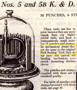
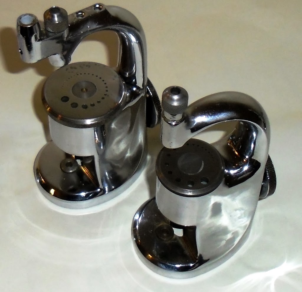
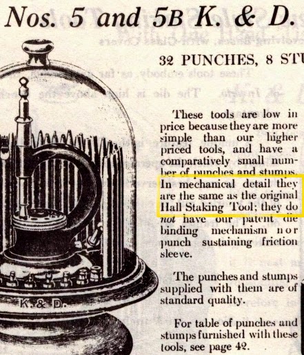
In the company’s catalog, K&D acknowledged their Model 5 & 5B staking sets as exact replicas of the Hall tool. They didn’t hide. They had no reason to do so. Hall’s factory burned down and no one wanted to rebuild it.

Click to enlarge

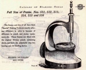
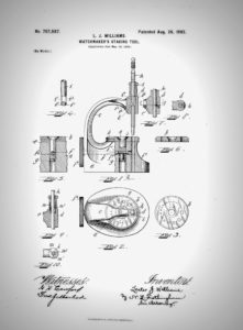
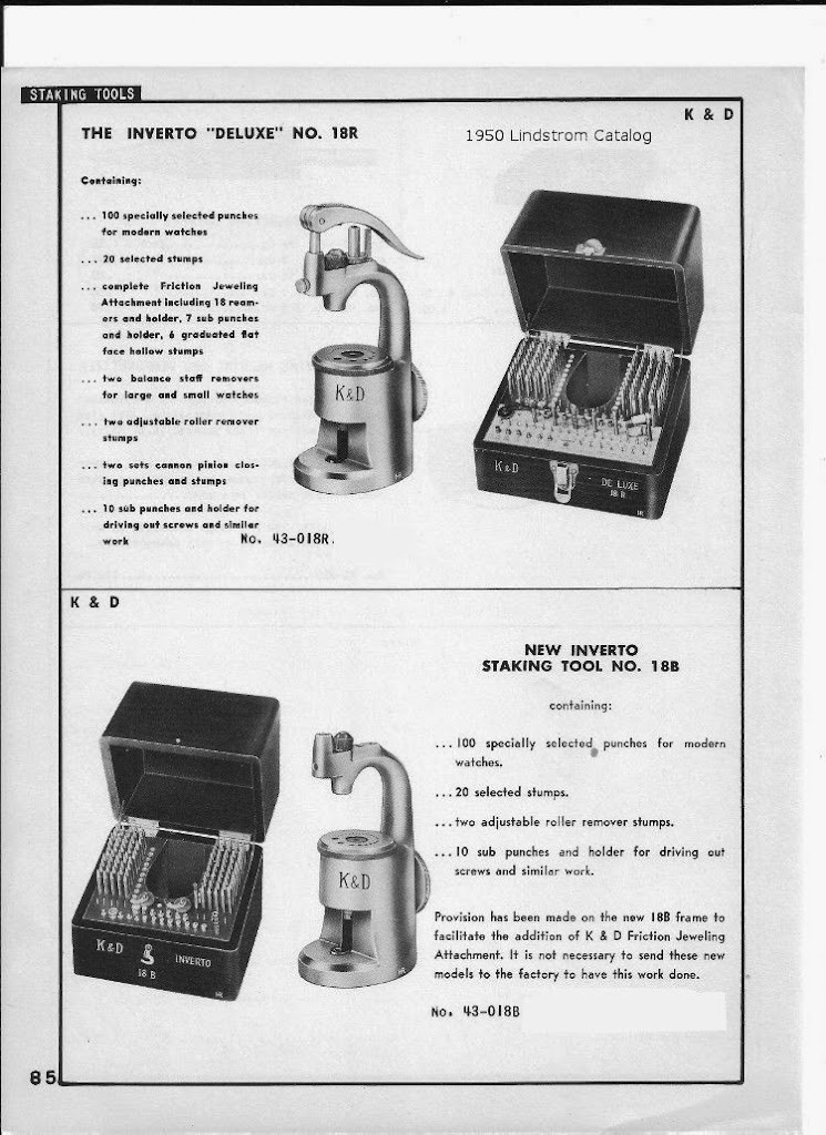
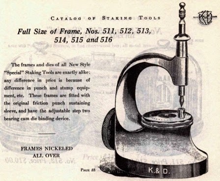
With financing and facilities in place, Mr. Crozier contacted Lester Williams and recruited him. Williams joined K&D and re-invented the staking tool calling it the “New Design”. K&D listed it as their model 500 series. Williams filed a patent for the New Design in 1902 and assigned it to Kendrick and Davis, a common practice followed even today between employee and employer.

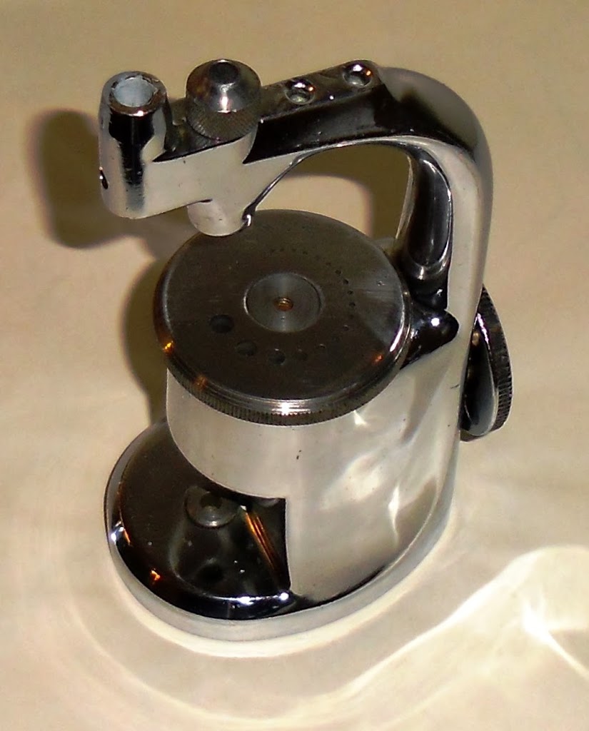
The 500 improved on the Hall design by changing the distribution of weight, which steadied the base. It also added features including a friction sleeve and a cam type die binder.  If you want to understand it, you can read Mr. Lawrence’s words below.

Why is this important? Gaining knowledge about watchmakers’ tools helps us learn to select and use them. Aside from that, you can hear the historic Mr. Lawrence’s voice in his words below.

Click to enlarge

My invention relates to improvements in watchmakers’ staking-tools, and has for its object the production of a tool of this character wherein the punch or plunger may be sustained within its guide in any desired position relative to the base to permit it to be withdrawn from and held free of the of the wheel without necessitating its complete withdrawal from the guide.


A further object is to provide a tool wherein the mechanism for setting the face-plate is capable of adjustment to facilitate the assembling of the tool, to compensate for wear through use on the various parts, or to accommodate this action to the requirements of the individual workman.
The invention consists in the novel features of construction hereinafter set forth and described, and more particularly pointed out in the claims hereto appended.
Referring to the accompanying drawings,
Click to enlarge

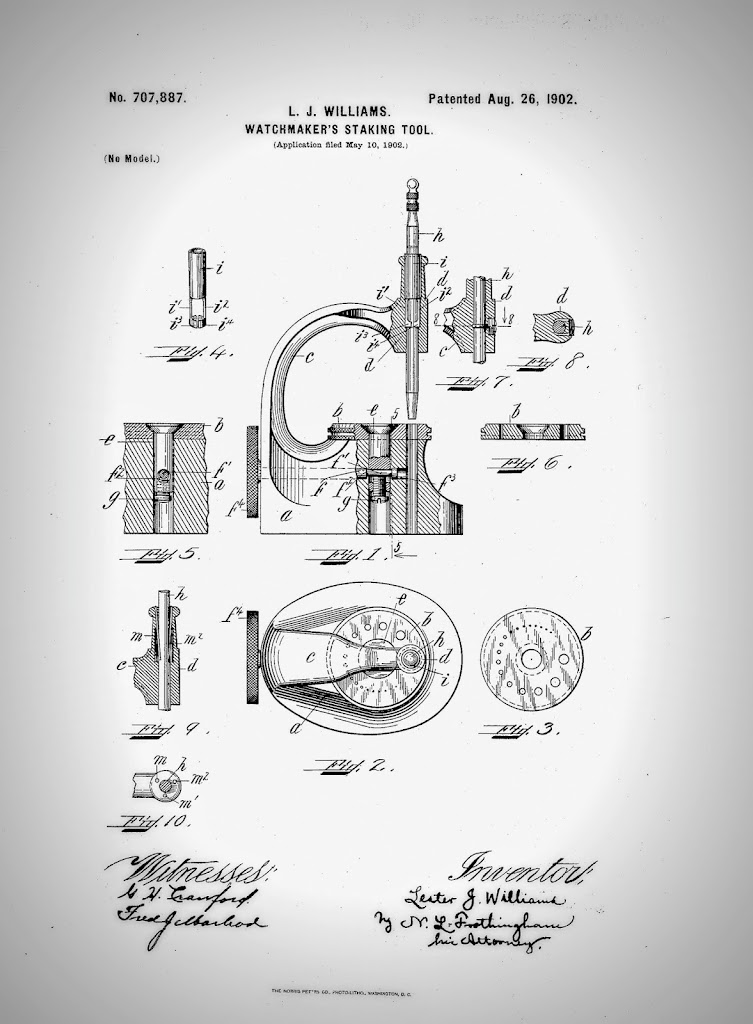
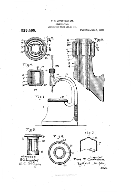
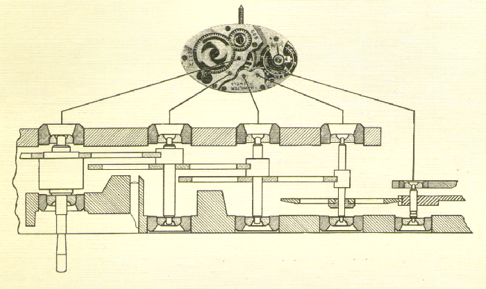
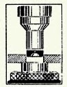
Figure 1 is a side elevation, partly in section, of a staking tool embodying the preferred form of my invention.

Fig. 2 is plan view thereof. Fig. 3 is a view of the bottom of the face-plate detached from the base.
Fig. 3 is a view of the bottom of the face-plate detached from the base.
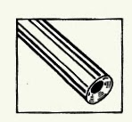
Fig. 4 is a view in perspective of the preferred form of the means of sustaining the punch or plunger.
Fig. 5 is a section on the line 5 5 of Fig. 1.
Fig. 6 is a sectional view of the face-plate detached from the base.
Fig. 7 is a view showing a modified form of the means for sustaining the punch or plunger.
Fig. 8 is a section on the line 8 8 of Fig. 7.
Fig. 9 is a view showing a still further modified form of said means, and
Fig. 10 is a plan of view of the modification shown in Fig. 9.
Like letters refer to like parts throughout the several views.
In the accompanying drawings, “a” indicates the base of the staking-tool, which is provided with the usual openings to permit the mounting thereon of the face-plate “b” and the escape of she expelled staff.
This base-plate also carries the arm or gooseneck “c”, which has formed thereon the guide-sleeve “d”, the opening in which is in alignment with the said escape-opening.
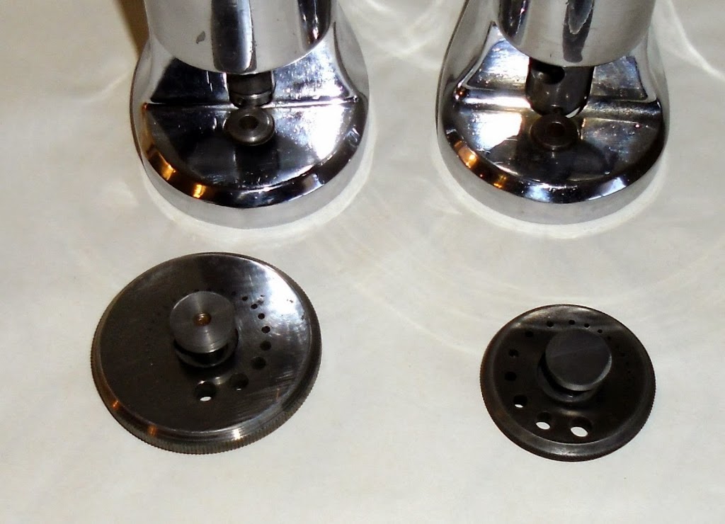
The face-plate “b” is provided with a central opening presenting a beveled surface to increase the area of frictional contact and insure a more perfect centering of the said plate, a vertical bearing-face, and a series of graduated openings equidistant from a common center to accommodate punch or plunger or other tool of different diameters, said plate being rotatable to permit said openings, respectively, to be brought into alignment  with said escape-opening and said guide, sleeve.
The face-plate is maintained in the proper position relative to said base a by means of the pivot—pin “e”, provided with a conical head fitted to the opening in and flush with said plate.
Extended through the lower part of this pin is an opening adapted to receive a shaft “f”, having in its length a reduced eccentric or cam portion “f”, acting in said opening, by means of which the pin e is drawn downward-or forced upward to bind said face-plate against it or release it from engagement with the base a to set it or permit it to be rotated, respectively.
This shaft “f” is seated in a bearing formed in the base “a”, said bearing being on both sides of the opening for said pivot-pin “e”.
The reduced eccentric or cam portion “f” forms shoulders adapted to bear upon reverse sides of the pivot-pin “e” to hold it in position.
This shaft extends without said base, and its exposed end is equipped with a knurled head by which it is manipulated.
The various parts are all finished and must be finely adjusted, as the device must act with the greatest accuracy.
To facilitate such adjustment, I provide a compensating-screw “g”, acting in the lower portion of the pivot-pin and against the eccentric or cam “f’”, by means of which the throw of said cam maybe regulated so as to overcome any slight irregularities in finish in assembling, wear from extensive use, or to suit the individual“ workman.
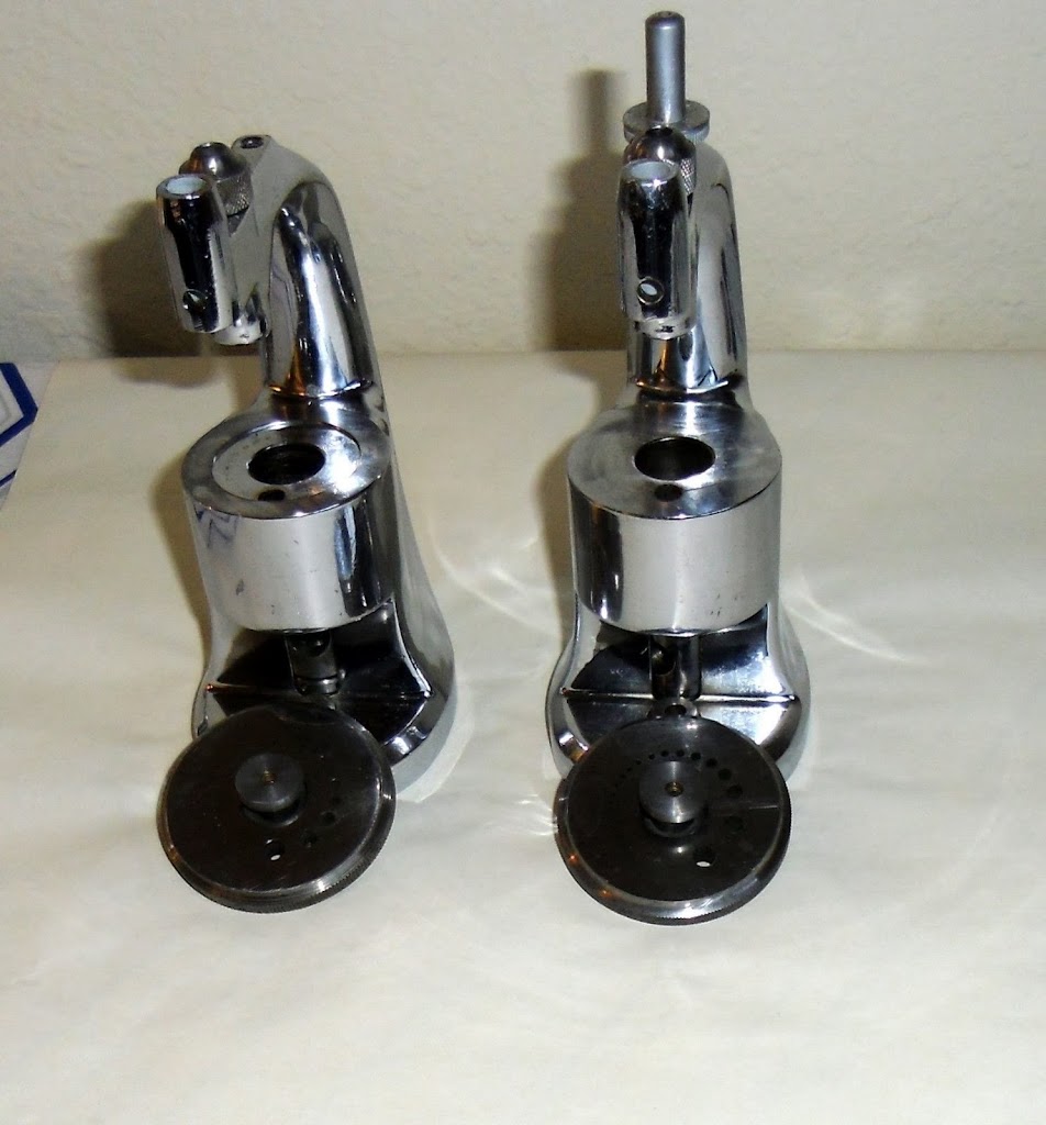
Acting in the guide—sleeve is a punch or plunger “h”; by means of which the staff is expelled from the wheel.
The guide-sleeve “d” is so arranged that said plunger may be sustained therein in any desired position relative to the face-plate, so as to be capable of being lifted free from the work to enable the temporary use of other tools without requiring the complete removal of the said plunger or punch.
In the preferred form of my invention, as shown in Figs. 1, 2, and 4, I enlarge the upper portion of the guide-sleeve “d” and countersink therein a sleeve “i”, provided with a plurality of spring-tongues “i1 12″, carrying, respectively, a semicircular bearing-face, as “i3 i4″, adapted to partially encompass and frictionally engage the punch or plunger “h”. This sleeve “i” may be secured within the guide sleeve d in any desired manner; but preferably it is made a “driving fit.”
In the modification shown in Figs. 7 and 8, I dispense with the sleeve “i” and merely employ a plurality of spring-tongues, as “j j’”, seated within the guide-sleeve “d” and partially encompassing the punch or plunger. These tongues are inserted through openings made in the guide-sleeve and are secured in this relation by means of a screw-plug “k”, hearing against their-outer ends.
In the modification shown in Figs. 9 and 10, I provide a plurality of spring-tongues “m1 m2″, which extend obliquely downward from the top of the guide-sleeve “d”, penetrating a chamber therein which is provided to permit a slight lateral movement of the lower ends of said springs. These tongues are secured in position in any desired manner; but preferably, holes are drilled, and said tongues are driven therein, being a tight fit.
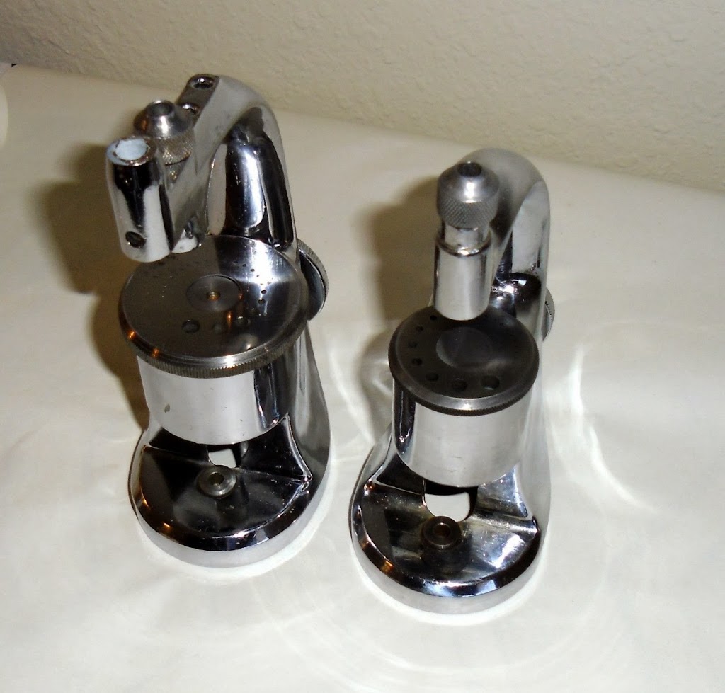
The operation of my staking-tool in so far as has not already been disclosed is as follows: The staff of the balance or other wheel having been fitted in the proper opening in the face-plate “b”, the clamping mechanism is released by means of the knurled head “f4″, which rotates the shaft “f” and the eccentric or cam portion thereof. This forces the pivot pin “e” upward until it is freed from engagement with the face-plate “b”. The said plate is then rotated until the proper opening is in alignment with the escape-opening in the base and with the plunger – guide sleeve. When it; is properly centered, it is set in this position by reversing the action of the cam. If it is found that; the throw of the cam is into properly release or clamp said plate or that there is a tendency to give too much motion to these parts to accomplish the desired result, this may be remedied by resetting the screw “g”. A smooth action of this mechanism is assured by reason of the double bearing for the shaft “f” and the shoulders “f2 and f3″, which are always in engagement with the pivot-pin e on reverse sides thereof, owing to the reduced diameter of the cam portion “f’”.
The operation of the sustaining spring tongues is substantially identical in the preferred form of my invention and in each of the modifications herein shown and described.
As the punch or plunger is inserted in the guide-sleeve d its end will spread the spring tongues, causing them to engage the sides thereof. This engagement will be sufficient to sustain the weight of the punch or plunger, but will not interfere to any extent with its reciprocation while in use.
If it be desired to examine the work in hand, to employ other tools upon it before the complete expulsion of the staff or to temporarily cease this operation for any other reason or purpose, it is merely necessary to raise the punch or plunger to the necessary height, and the spring-tongues will hold it in this position until it is desired to resume its use. This not only facilitates the work in hand, but obviates the necessity of a repeated refitting of the plunger to the guide-sleeve and the resulting annoyance.
It is not my intention to limit my invention to the precise construction herein shown and described, as it is apparent that there may be many deviations therefore without departing from the spirit of my invention.
Having described the invention, what I claim as new, and desire to have protected by Letters Patent, is—
1. In a staking-tool, in combination a perforated base, a punch or plunger, a guide therefore, and means adapted to frictionally engage said punch or plunger whereby said punch or plunger may be sustained in said guide in any desired position relative to said base.
2. In a staking-tool, in combination a perforated base, a punch or plunger, a guide therefore, and. means comprising a plurality of spring-tongues adapted to engage said punch or plunger whereby it may be sustained in said guide in any desired position relative to said base.
3. In a staking-tool, in combination a perforated base, a punch or plunger, a guide therefore, a means comprising a sleeve countersunk in said guide and a plurality spring-tongues carried thereby and adapted to engage said punch or plunger whereby it may be sustained in said guide in any desired position relative to said base.
4. In a staking-tool, in combination a perforated base, a punch or plunger, a guide therefore, and means comprising a sleeve countersunk in said guide a plurality of spring tongues carried thereby and bearing-surfaces carried by said tongues and adapted to engage said punch or plunger whereby it may be sustained in any desired position relative to said base.
5. In a staking-tool, in combination, a perforated base, a punch or plunger, a rotatable face-plate carried by said base, a pivot-pin connecting said base and said plate, a cam whereby said pivot-pin is reciprocated to release or clamp said face-plate and means comprising an adjustable contact carried by said pivot~pin and acting against said cam whereby the throw of said pivot—pin by said cam maybe regulated.
6. In a staking-too1, in combination, a perforated base, a punch or plunger, a rotatable face-plate carried by said base, a pivot-pin connecting said base and said cam whereby said pivot-pin is reciprocated to release or clamp said face-plate and a set-screw carried by said pivot-pin.
7. In a staking-tool, in combination a perforated base, a punch or plunger, a rotatable face-plate carried by said base, a pivot-pin connecting said base and said face-plate having an opening extending there through, a shaft seated in said base and extending through said opening a portion of said shaft being reduced and eccentric, said portion being within the opening in said pivot-pin, whereby shoulders are formed to bear upon the reverse sides of said pivot-pin, and said face-plate may be released from or clamped against said base.
Posted on

K&D and C&E Marshall Moseley Staking Tool Manuals

You will probably discover difficulty in finding staking tool manuals. The original 1910 K&D book – Staking Tools and How to Use Them is hard to come by.  You will find numerous titles under that name and even reprints. The reprints are either catalogs from the 1950’s or the latter 108 of the original 163 pages. Those smaller books lack important information. Even so, they are also hard to find and high priced.

The NWCCA Library has a copy of the original 1910 K&D book, but will not lend it out. You have to visit their Library and read it there.

The original 163 page book is now available in pdf form on eBay.

Many watchmakers and enthusiasts find ample information in Henry Fried’s and Donald De Carle’s books, but neither focuses on the staking set itself.

I gathered pdf’s of the 1910 partial reprint and additional catalogs and user manuals. You can download them here.

If you are just getting started, these e-books can be helpful and you won’t have to do endless searches (as I have) to find them. You may download them by clicking on the link.
None of these e-books are of the original Kendrick & Davis Tools Book from 1910. That books is 163 pages and extremely rare.
Download
Download
Download
Download

If you want to take a look at the current Staking Sets for sell on eBay, use this link:

Posted on

K&D Staking Tool – Friction Sleeve Patent Description

Publication number US923495 A
Publication type Grant
Publication date Jun 1, 1909
Filing date Aug 21, 1908
Priority date Aug 21, 1908
Inventors Frank R Cunningham*
Original Assignee Kendrick & Davis
Classifications (1)
External Links: USPTOUSPTO AssignmentEspacenet
DESCRIPTION 
F. CUNNINGHAM.
STAKING TOOL. APPLICATION FILED Aug 21 1908.
Patented June 1, 1909.
WASHINGTON, D.C.
UNITED STATES PATENT OFFICE.
FRANK R. CUNNINGHAM, OF MEDFORD, MASSACHUSETTS,
ASSIGNOR TO KENDRICK & DAVIS, OF LEBANON, NEW HAMPSHIRE.
STAKING-TOOL.

Specification of Letters Patent.
Patented June 1, 1909.
Application filed August 21, 1908. Serial No. 149,725.

To all whom it may concern:

Be it known that I, FRANK CUNNINGHAM, of Medford, in the county of Middlesex and State of Massachusetts, have invented certain new and useful Improvements in Staking-Tools, of which the following is a specification.

This invention relates to staking tools for jewelers and watchmakers work, and has relation to a clamp by which the punches, centering tools or other operating tools used in this sort of apparatus may be held unyielding in any position, and may be readily released.

The invention consists in spring clamps and a holder therefore, which are associated with the rest of the staking tool so that they may press unyielding upon and grasp the shank of the operating tool, but may be released by a simple rotary movement of the holder.

Of the accompanying drawings ,Figure 1 represents an elevation of a staking tool having my improvement applied thereto.

Fig. 2 represents a vertical section through the head of the staking tool and the attachment. Fig. 3 represents a horizontal section of the staking tool head and of the attachment constituting my invention. Fig. 4 represents a sectional view taken on line 44 of Fig. 3. Fig. 5 represents an elevation of the upper part of the tube which is set into the head of the staking tool and upon which the attachment constituting my invention is mounted. Fig. 6 represents a plan view of the bottom of the clamp holder forming part of my invention. Fig. 7 represents a perspective view of one end of one of the spring clamps.

The same reference characters indicate the same parts in all the figures.

A staking tool is shown in Fig. 1. and consists as usual of the base 1 having a die plate 2 and a curved neck 3 with a head 4 which overhangs the die plate. This head, as appears most clearly in Fig. 2, is bored vertically, and contains a tube 5 having along latitudinal bore or passage through which the punch centering member or other operating tool used in connection with a staking tool, is passed. My invention has to do entirely with a device by which the operating tool may be retained against displacement through the passage by gravity, while permitting such ,tool to be moved by the application of a slightly greater force, and with the means by which the device may be rendered inoperative by a single slight movement.

 The device constituting the invention consists of a clamp holder 6 in the form of a sleeve, and spring clamps 7 and 8 contained in such sleeve. The sleeve is journaled upon a portion of the tube 5 which projects above the head 4 and is contained between the upper end of this head and a flange 9 on the tube. The clamps are in the form of spirally curved flat springs which are contained within the sleeve 6, the interior diameter of which is sufficiently greater than the tube 9 to contain the springs and permit flexibility.

At or near the upper end of the clamp holder is an internal flange 10, the annular surface of which. fits an upper bearing surface 11 of the tube 5, while the other end of the sleeve is recessed to receive an annular plate 12. In the angle between the side walls and flange of the sleeve is a groove 13, and in the plate 12 near its periphery are notches 14. This groove and these notches are provided to receive lugs 15 and 16 on opposite sides near the outer ends of the springs which form the clamps. In assembling the parts, these springs are placed in the clamp holder 6 with their outer ends lying against the cylindrical walls thereof and their lugs 15 entering the groove 13.

They are adjusted so that the lug 16 of each will enter one of the notches 14 of the plate 12, and the latter plate is then put in place. It is preferably made so that it will fit tightly into the end of the holder 6 and abut against shoulder 17 formed therein.

The inner ends of the springs are straight and parallel with each other, lying on opposite sides of the center of the clamp holder, and when not distorted, located at a distance from one another less than the diameter of the shank of an operating tool. .Then the clamp holder is mounted upon the hearing tube 5 the clamps lie on opposite sides of the latter. They are enabled to make contact with and grasp the shank of the operating tool by reason of the fact that the tube 5 is slabbed off on opposite sides to a depth sufficient to provide openings or slots 18 and 19 which communicate with the internal bore or passage, and are of sufficient length to admit the spring clamps.

When the clamp holder is in the position shown in Fig. 3, the clamps enter the openings 18 and 19 and bear against the shank of the operating tool, grasping the same with a yielding pressure, which is sufficient to hold the operating tool in any position which it may occupy and prevent it from slipping downward against the die plate.

In Fig 1 an operating tool is represented by the punch 20, this figure illustrating how the tool is held up by the spring clamps. Upon rotating the clamp holder 6 slightly in either direction, the ends of the springs which form the clamps abut against the sides of the tube 5 adjacent the openings, and are drawn outward by the wedging action of the same so as to be removed from contact with the tool shank. The operating tool is then free.

Thus the parts of the tube adjacent these openings, or, in other words, the walls of the openings, constitute abutments which, when the clamp holder is in one position, retain the springs out of engagement with the operating tool and, when the holder is in another position, allow the springs to press with a yielding frictional engagement against the tool.

I claim

1. A staking tool having a head provided with a passage through it for admitting an operating tool, a spring friction member supported on said head and arranged to bear normally with a yielding frictional pressure upon such tool, and means for disengaging said friction member from the operating tool.

2. A staking tool having a head provided with a passage through it for admitting an operating tool, a holder mounted movably with respect to said head, a spring friction member carried by said holder, and means constructed to hold said friction member out of contact with such operating tool when said holder is in one position, and to permit said member to bear with a yielding frictional pressure on the tool when the holder is in another position.

3. A staking tool having a head provided with a passage through it for admitting an operating tool, a holder mounted rotarily on said head, a spring carried by said holder and arranged to bear with a yielding frictional pressure against such operating tool, and an abutment located beside such passage in the path traversed by said spring when rotated, whereby rotation of said holder causes the spring to engage said abutment and to be withdrawn thereby from engagement with the operating tool.

4. In a staking tool, a head having a tubular bearing for an operating tool, a holder rotarily mounted on said head, springs carried by said holder arranged to enter slots in the sides of said tubular bearing and press yieldingly against the shank of such operating tool, and adapted to be withdrawn from contact with the tool when the holder is rotated.

5. In a staking tool, ahead, a tube set in said. head having a bore to receive an operating tool and having an opening in its side, a sleeve rotarily mounted on said tube, and a spring held in said sleeve with its end arranged tangentially of the shank of said operating tool, and located so as to enter such opening and press against said shank, being withdrawn from contact therewith when the sleeve is rotated.

6. A staking tool having a head provided with a passage through it for admitting an operating tool, a holder mounted movably with respect to said head, a spring friction device carried by said holder for holding such operating tool with a yielding pressure, and an abutment against which said friction device is brought by movement of said holder and by which said device is Withdrawn from engagement with the operating tool.

7. In a staking tool, a head having a passage to contain an operating tool and provided with a lateral opening affording access to the passage, a sleeve rotatably mounted on said head, and a spring carried by said sleeve arranged to enter said lateral opening and bear yieldingly on the shank of the operating tool to serve as a frictional retainer therefor, said spring being caused to Withdraw from said shank by bearing against an edge of the opening when the sleeve is rotated.
8. In a staking tool, an independent clamp holder, spring clamps carried thereby adapted to grasp the shank of an operating tool yieldingly, and provisions for causing said clamps to release the operating tool While said holder remains in connection with the staking tool.

9. In a staking tool, an independent clamp holder, spring clamps carried thereby adapted to grasp the shank of an operating tool yieldingly, and fixed abutments on the staking tool arranged so as to be engaged by said clamps, when the holder and clamps are moved out of grasping position, and thereby cause withdrawal of the clamps from said shank.

10. A staking tool having a head, a tube et into said head having a bore to receive an operating tool, a clamp holder journaled on a part of said tube, and spring clamps carried by said holder; the tube having openings communicating with its bore in the zone surrounded by the holder into which said clamps extend to grasp the shank of said operating tool when the holder is in one position and from which the clamps are retracted by abutting against the sides of the openings when the holder is turned into a different position.

11. In a staking tool, a clamp holder consisting of a sleeve having an internal flange near one end and an annular plate attached removably to the other end thereof, and spirally coiled springs held at their outer ends between said flange and plate, their inner ends being free and arranged to grasp between them the shank of an operating tool.

12. In a staking tool, a clamp holder connects ends being free and arranged to grasp resisting of a sleeve having an internal flange between them, the shank of an operating tool near one end and an annular plate attached.

In testimony whereof I have affixed my removably to the other end thereof,  said signature, in presence of two witnesses observing the plate having notches, and spirally coiled springs held at their outer ends between, said FRANK CUNNINGHAM’S flange and plate, each spring having a lug returning one of the notches of said plate and 
held thereby against displacement.

Witnesses:

 A. O. RATIGAN.
 C. F. BROWN,

CLASSIFICATIONS
Cooperative Classification G04D3/04
*Mr. Cunningham created watchmakers hand tools for Hammel & Riglander & Co. New York, NY. 
Posted on

K&D Staking Tool – Off-On Addition to Friction Sleeve

Publication number US923495 A
Publication type Grant
Publication date Jun 1, 1909
Filing date Aug 21, 1908
Priority date Aug 21, 1908
Inventors Frank R Cunningham*
Original Assignee Kendrick & Davis
Classifications (1)
External Links: USPTOUSPTO AssignmentEspacenet
DESCRIPTION 
F. CUNNINGHAM.
STAKING TOOL. APPLICATION FILED Aug 21 1908.
Patented June 1, 1909.
WASHINGTON, D.C.
UNITED STATES PATENT OFFICE.
FRANK R. CUNNINGHAM, OF MEDFORD, MASSACHUSETTS,
ASSIGNOR TO KENDRICK & DAVIS, OF LEBANON, NEW HAMPSHIRE.
STAKING-TOOL.

Specification of Letters Patent.
Patented June 1, 1909.
Application filed August 21, 1908. Serial No. 149,725.

To all whom it may concern:

Be it known that I, FRANK CUNNINGHAM, of Medford, in the county of Middlesex and State of Massachusetts, have invented certain new and useful Improvements in Staking-Tools, of which the following is a specification.

This invention relates to staking tools for jewelers and watchmakers work, and has relation to a clamp by which the punches, centering tools or other operating tools used in this sort of apparatus may be held unyielding in any position, and may be readily released.

The invention consists in spring clamps and a holder therefore, which are associated with the rest of the staking tool so that they may press unyielding upon and grasp the shank of the operating tool, but may be released by a simple rotary movement of the holder.

Of the accompanying drawings ,Figure 1 represents an elevation of a staking tool having my improvement applied thereto.

Fig. 2 represents a vertical section through the head of the staking tool and the attachment. Fig. 3 represents a horizontal section of the staking tool head and of the attachment constituting my invention. Fig. 4 represents a sectional view taken on line 44 of Fig. 3. Fig. 5 represents an elevation of the upper part of the tube which is set into the head of the staking tool and upon which the attachment constituting my invention is mounted. Fig. 6 represents a plan view of the bottom of the clamp holder forming part of my invention. Fig. 7 represents a perspective view of one end of one of the spring clamps.

The same reference characters indicate the same parts in all the figures.

A staking tool is shown in Fig. 1. and consists as usual of the base 1 having a die plate 2 and a curved neck 3 with a head 4 which overhangs the die plate. This head, as appears most clearly in Fig. 2, is bored vertically, and contains a tube 5 having along latitudinal bore or passage through which the punch centering member or other operating tool used in connection with a staking tool, is passed. My invention has to do entirely with a device by which the operating tool may be retained against displacement through the passage by gravity, while permitting such ,tool to be moved by the application of a slightly greater force, and with the means by which the device may be rendered inoperative by a single slight movement.

 The device constituting the invention consists of a clamp holder 6 in the form of a sleeve, and spring clamps 7 and 8 contained in such sleeve. The sleeve is journaled upon a portion of the tube 5 which projects above the head 4 and is contained between the upper end of this head and a flange 9 on the tube. The clamps are in the form of spirally curved flat springs which are contained within the sleeve 6, the interior diameter of which is sufficiently greater than the tube 9 to contain the springs and permit flexibility.

At or near the upper end of the clamp holder is an internal flange 10, the annular surface of which. fits an upper bearing surface 11 of the tube 5, while the other end of the sleeve is recessed to receive an annular plate 12. In the angle between the side walls and flange of the sleeve is a groove 13, and in the plate 12 near its periphery are notches 14. This groove and these notches are provided to receive lugs 15 and 16 on opposite sides near the outer ends of the springs which form the clamps. In assembling the parts, these springs are placed in the clamp holder 6 with their outer ends lying against the cylindrical walls thereof and their lugs 15 entering the groove 13.

They are adjusted so that the lug 16 of each will enter one of the notches 14 of the plate 12, and the latter plate is then put in place. It is preferably made so that it will fit tightly into the end of the holder 6 and abut against shoulder 17 formed therein.

The inner ends of the springs are straight and parallel with each other, lying on opposite sides of the center of the clamp holder, and when not distorted, located at a distance from one another less than the diameter of the shank of an operating tool. .Then the clamp holder is mounted upon the hearing tube 5 the clamps lie on opposite sides of the latter. They are enabled to make contact with and grasp the shank of the operating tool by reason of the fact that the tube 5 is slabbed off on opposite sides to a depth sufficient to provide openings or slots 18 and 19 which communicate with the internal bore or passage, and are of sufficient length to admit the spring clamps.

When the clamp holder is in the position shown in Fig. 3, the clamps enter the openings 18 and 19 and bear against the shank of the operating tool, grasping the same with a yielding pressure, which is sufficient to hold the operating tool in any position which it may occupy and prevent it from slipping downward against the die plate.

In Fig 1 an operating tool is represented by the punch 20, this figure illustrating how the tool is held up by the spring clamps. Upon rotating the clamp holder 6 slightly in either direction, the ends of the springs which form the clamps abut against the sides of the tube 5 adjacent the openings, and are drawn outward by the wedging action of the same so as to be removed from contact with the tool shank. The operating tool is then free.

Thus the parts of the tube adjacent these openings, or, in other words, the walls of the openings, constitute abutments which, when the clamp holder is in one position, retain the springs out of engagement with the operating tool and, when the holder is in another position, allow the springs to press with a yielding frictional engagement against the tool.

I claim

1. A staking tool having a head provided with a passage through it for admitting an operating tool, a spring friction member supported on said head and arranged to bear normally with a yielding frictional pressure upon such tool, and means for disengaging said friction member from the operating tool.

2. A staking tool having a head provided with a passage through it for admitting an operating tool, a holder mounted movably with respect to said head, a spring friction member carried by said holder, and means constructed to hold said friction member out of contact with such operating tool when said holder is in one position, and to permit said member to bear with a yielding frictional pressure on the tool when the holder is in another position.

3. A staking tool having a head provided with a passage through it for admitting an operating tool, a holder mounted rotarily on said head, a spring carried by said holder and arranged to bear with a yielding frictional pressure against such operating tool, and an abutment located beside such passage in the path traversed by said spring when rotated, whereby rotation of said holder causes the spring to engage said abutment and to be withdrawn thereby from engagement with the operating tool.

4. In a staking tool, a head having a tubular bearing for an operating tool, a holder rotarily mounted on said head, springs carried by said holder arranged to enter slots in the sides of said tubular bearing and press yieldingly against the shank of such operating tool, and adapted to be withdrawn from contact with the tool when the holder is rotated.

5. In a staking tool, ahead, a tube set in said. head having a bore to receive an operating tool and having an opening in its side, a sleeve rotarily mounted on said tube, and a spring held in said sleeve with its end arranged tangentially of the shank of said operating tool, and located so as to enter such opening and press against said shank, being withdrawn from contact therewith when the sleeve is rotated.

6. A staking tool having a head provided with a passage through it for admitting an operating tool, a holder mounted movably with respect to said head, a spring friction device carried by said holder for holding such operating tool with a yielding pressure, and an abutment against which said friction device is brought by movement of said holder and by which said device is Withdrawn from engagement with the operating tool.

7. In a staking tool, a head having a passage to contain an operating tool and provided with a lateral opening affording access to the passage, a sleeve rotatably mounted on said head, and a spring carried by said sleeve arranged to enter said lateral opening and bear yieldingly on the shank of the operating tool to serve as a frictional retainer therefor, said spring being caused to Withdraw from said shank by bearing against an edge of the opening when the sleeve is rotated.
8. In a staking tool, an independent clamp holder, spring clamps carried thereby adapted to grasp the shank of an operating tool yieldingly, and provisions for causing said clamps to release the operating tool While said holder remains in connection with the staking tool.

9. In a staking tool, an independent clamp holder, spring clamps carried thereby adapted to grasp the shank of an operating tool yieldingly, and fixed abutments on the staking tool arranged so as to be engaged by said clamps, when the holder and clamps are moved out of grasping position, and thereby cause withdrawal of the clamps from said shank.

10. A staking tool having a head, a tube et into said head having a bore to receive an operating tool, a clamp holder journaled on a part of said tube, and spring clamps carried by said holder; the tube having openings communicating with its bore in the zone surrounded by the holder into which said clamps extend to grasp the shank of said operating tool when the holder is in one position and from which the clamps are retracted by abutting against the sides of the openings when the holder is turned into a different position.

11. In a staking tool, a clamp holder consisting of a sleeve having an internal flange near one end and an annular plate attached removably to the other end thereof, and spirally coiled springs held at their outer ends between said flange and plate, their inner ends being free and arranged to grasp between them the shank of an operating tool.

12. In a staking tool, a clamp holder connects ends being free and arranged to grasp resisting of a sleeve having an internal flange between them, the shank of an operating tool near one end and an annular plate attached.

In testimony whereof I have affixed my removably to the other end thereof,  said signature, in presence of two witnesses observing the plate having notches, and spirally coiled springs held at their outer ends between, said FRANK CUNNINGHAM’S flange and plate, each spring having a lug returning one of the notches of said plate and 
held thereby against displacement.

Witnesses:

 A. O. RATIGAN.
 C. F. BROWN,

CLASSIFICATIONS
Cooperative Classification G04D3/04
*Mr. Cunningham created watchmakers hand tools for Hammel & Riglander & Co. New York, NY. 
Posted on

Instructions for Use – K&D Kendrick & Davis Balance Staff Remover 50 & 50B

Directions

Select proper hole in Staking Tool die to let hub of staff through: place balance with staff to be removed in same. Set remover over same and insert its pu!1ch through staking tool and
main body of remover. Holding punch in position over.. pivot with finger of right hand tighten knurled remover nut upwards against staking tool arm.

Stop arm of remover will swing against body of Staking Tool and prevent body of tool turning while tightening knurled sleeve. Do not over tighten this sleeve:

it is not necessary. Now strike punch a sharp blow with light hammer and staff will come
out without injury to Balance; riveting of staff simply being sheared off.

NO. 50 BALANCE STAFF REMOVER

In ordering our No. 50 measure the gap between your Staking Tool die and bottom of Goose Neck. Table below will show the size

No. 50 which will fit your Staking Tool.

“K.& D” No. 50 Will fit any S. T. Staking Tools No. Sizes Die Gap of #18 Series #600 Series
1 1-8in. ‘7-8in. 1 3.16in. 1 1-16in.

All the above No. 50 sizes can be furnished for Bracelet size Balances but in ordering add
the letter “B”.


Posted on

K&D (Kendrick and Davis) Staking Tools – Identification and Information Series: 16AH

In 1909, K&D build numerous versions of its staking sets. Each version filled a specific need. The text in this advertisement explains the advantage of two features the company offered.

The Text Reads:

[Click on Image to Enlarge]

Ball bearing bases are popular because their many good qualities – their weak point being that no adequate hold is afforded by which they may be lifted from place to place on the bench; it is always necessary for the watchmaker to use both hands.

The new handle completely removes this difficulty; it is neat and strong; fastened to the base by three substantial steel screws, inserted from the inside, therefore, invisible. These handles fit any K.& D. ball bearing base, but should be attached at the factory.

The standard staking sets came in either a wooden box or the dome covered round bases of which three existed. Variations of the following sets came with these frames:

Inverto No. 17
Inverto No. 18 with On or Off Punch sustaining Device
Inverto No. 17 A and 18A on ball bearing bases
New Design, but not Inverto: No. 12B, 13B, 14B, 15B, 16B
Without die binding and friction sleeve: No. 5 and 5B

The 16A & 16B used the punches you may find with a letter preceding a number. For example,
A 1  Stretching balance arms
B42 Flat Faced Hollow Punches
C79 Taper Mouth Closing Punch

The lettered punches are longer than the Inverto punches, e.g., No. 44. K&D had to shorten the punches to work with the Inverto frames.

Posted on

Kendrick & Davis K&D Friction Jeweling Tools for the 18R Deluxe & a Tutorial

The K&D Model 18R Deluxe came with three separate jeweling sets. They include those pictured below:

  • 321 – Seven Friction Jewel Subpunches
  • 322B – 18 Jewel Size Reamers and Holder
  • 324 – Six Hollow Friction Jeweling Stumps

I bought these sets separately. I don’t like the 18R box as it created difficulty when I reached for punches. The reamers have sharp ends and I found myself hitting them. On occasion, I cut myself. Also, I don’t use jeweling tools that often.

I also prefer the 600 series and the No. 17 staking frames. My jeweling tools stay in a drawer.

Below is a tutorial I posted in an earlier post. It may help you understand the use of these tools.

What’s Friction Jeweling any way?

In 1924, Hamilton took credit for the first improvement in jeweling since Nicolas Facio patented the use of jewels in watches in 1704. Hamilton called their system “improved jeweling”. Now, the Swiss claim they invented friction jeweling, but they haven’t produced any names or dates to substantiate their claim that I can find.

Let’s look at what Hamilton said. First, they claimed that as a  result of years of experimentation and research, that they came up with the “Hamilton Improved Friction Jeweling” method.

They then demonstrated it on the 989 18/0 watch movement.

While difficult to decipher from the image above, the 989 did not have bezel rings holding their jewels in place. You can see the difference in the two types of jeweling methods in the  photos below.

Hamilton released its first 987 caliber wristwatch movement with beveled edged jewels.This method held the jewels in with a screw-held ring. If you take a close look at the image on the left, then you can see two small screws holding a ring over each jewel. Hamilton released the next version of the 987 with friction jewels after the 989 proved it worked.

Little information exists on who actually manufactured the first friction jewels. Since Hamilton bought their jewels from Swiss companies, we can guess that the jewels came from Switzerland. Regardess, design and manufacturing techniques for watch jewels improved around the time Hamilton produced the 989 and subsequently. the 987E.  Hamilton began using jewels able to hold their position with friction alone, which cut down on time and effort to manufacture and service movements.

In this small post, we can look at how K&D and Moseley recommended replacing friction jewels.

The method for replacing a broken or dysfunctional jewel involves:

  1. Measuring
  2. Knocking out the old jewel and
  3. Setting a new jewel.

Once you discover the simplicity of friction jeweling, anxiety about it will fade. Let’s go through the steps so we can move forward in our understanding of watch maintenance and repair.

1. Select a jeweling stump with a hole larger than the jewel needing replacement. Place the stump in the die plate of your staking tool and center.

2.      Select a pusher smaller than the jewel needing replacement. Place the pusher in its holder and secure it in the frame sleeve.

Staking Frame with Micrometer

3. With the exception of Balance Jewels, use the pusher to adjust the micrometer. For example, place a watch bridge on the stump facing up. Rest the pusher on the old jewel and adjust your micrometer to limit the movement of the pusher. Jot down the setting on a piece of paper and use it when setting the depth for the replacement jewel.

4. Lower the micrometer stop and press on the old jewel to remove it.

5.  If you have friction type jewel with an undamaged hole, skip the next two steps.

6. If you need to refinish the hole, pick out one of the reamers. Make sure it is large than the existing hole.

7. You can now ream the jewel hole for your replacement jewel.

8. Again, use the holder for the reamer and place it through the staking frame’s sleeve.

9. Don’t let the reamer go further than a millimeter into the hole.

10. Turn it to create a smooth and appropriate size hole.

11. Use a cone miller to remove any burrs from the edges of the hole.

12.  Now, you can place the jewel in the reamed out hole. Make sure the oil cup is face down.

13.  Use the pusher from step 2. Set the micrometer as you did in step 3.

14.  Rest the pusher on the new jewel and then press down the jeweling lever on your frame. The micrometer will stop it from pushing the jewel past the proper fit.

15.  Check to see if the watch part using the hole has a proper end-shake. You’ll need to rely on whatever literature exists for your watch.


16.  If you have to reset the jewel, adjust the micrometer stop and reset the jewel.

17.  If friction type settings are loose in the plates or bridges of your watch, you’ll need to tighten it by closing the hole.

18.  Use a taper mouth closing punch. (K&D punches 31 through 38A. Moseley  E1 through E9).

19.  A taper mouth closing punch draws soft metal in and reduced the size of the a jewel hole.

20.  Select a punch slightly smaller than the setting.

21.  Place the setting on a flat face stump, center it and tap the punch. You will see a groove that will help create a tight fit. Proceed at a slow pace as this tightening process will incorporate trial and error.

I wrote this as a high level view of the jeweling process. The entire scope of jeweling is a body of knowledge in itself. Never-the-less, I found this information helpful. It took the mystery out of the process for me.

[Click on image to enlarge]

Posted on

Adjustable Roller Removers and the Kendrick & Davis K&D Model 305 v Rex

Students of horology tend to focus on mechanical watches. I didn’t work on a quartz movement for years and when I did, it reminded me of “electric shop” in high school. Watchmakers have a fascination with mechanical movements and that means escape mechanisms and specifically the balance wheel.

Most of the work I have done in restoration involves replacing balance staffs. If you can re-staff a balance, you can by broken watches on eBay inexpensively. I’m trying to keep away from the word cheap.

Most of the Hamilton watches I purchase have broken balance staffs. That means removing the balance assembly, the collet and hairspring and the roller table. Not many tools for removing collets exist. I use a K&D collet fork for pocket watches (size 12-18) and a Bergeon for bracelets (size 0-22/0).

Once we remove the collet and hairspring, we need to remove the roller. A plethora of roller tools exist out there. In speaking with numerous watchmakers, most have said that they used the Rex Roller Remover. That surprised me. I had always used the K&D 305, because that’s the only tool we had in the lab.

Since the end of World War II, watch schools have used K&D staking sets and the majority of those came with the 305 adjustable table removers – figures 3 and 6. In practice, however, watchmakers bought their tools from a variety of sources. I didn’t know that.

I see many Rex sets on eBay and other sites on the Internet. Those funny black cylinders seem to show up more often than not. They also sell for less than the K&D.

I decided to look into adjustable roller removers and found that K&D came late to the market. Roller remover stumps almost always appeared in staking sets, but Rex invented the adjustable sumps. I’ve also found that they have a superior configuration.

Figure 1 came from an old supply house catalog. Figure 2 shows how the tool worked and Figure 4 explains how it works. The Rex uses a tiny rod to tighten the stump’s teeth as they settle between the roller table and balance wheel. K&D requires a staking frame and the user to tighten the stump by turning either the chrome bottom (Figure 6)  or the wing (on the older model Figure 3).

K&D had some difficulty achieving market adoption for the 305. The company included it in most of the staking boxes they sold beginning in 1946. They even changed the look of their original 305 (Figure 3) to resemble the Rex. Finally, they packaged the 305 to look like the Rex – Figure 7.

I have started using the Rex. The jury is still out between it and the early 305. I suggest you look at the shape of the stump head. Each iteration differs. Regardless, don’t dismiss the Rex. She might now look as hot as the younger model, but she’s a bargain.

Figure 1
Figure 2
Figure 3
Figure 4
[Click on image to enlarge]
Figure 5
Figure 6
Figure 7
Posted on

Kendrick and Davis K&D Tool Identification Guide

These catalog images can help people identify tools they may wish to purchase or sale on eBay or other sites. We see a surprising number of preowned watchmaker’s tools up for auction during warm months. During the late spring through late fall, estate sales proliferate the market. You will begin seeing more watchmaker’s tools for sale without descriptions. If you’re in the market, you will find that “being informed” makes a huge difference when it comes to paying the proper price for items and getting a great deal.

You may also discover that someone ran into a watchmaker’s estate and thought they struck gold. You can tell when the put a $150 staking set up and ask $850 for it.

These are K&D brand tools. The popularity of K&D Staking Sets have made many of their other tools popular. In fact, K&D tools are collectors favorites.

[Click on an image to enlarge it]

Hairspring Collect Remover
Jewel Pusher
Bench Keys
Watch Keys
Gold Tipped Oiler
Arbor & Saw
Brass Head Mallet
Brass & Fiber Faced Mallet
Case Opener
Bench Knife
Watch Mainspring Winder
Wrist Watch Crown Winder
Watch Mainspring Winder
Watch Mainspring Winder
Pin Pusher
Pin Vices
Counterbores & Sinks
Jewel Screw Drivers
Jewel Screw Drivers
Jewel Screw Drivers – Five
Six Double Blade Screw Drivers
Waltham Screw Drivers
Adjustable Roller Stumps
Balance Truing Wrench
Sensible Hand Remover
Sub Punches
Friction Jeweling Sub Punches
Roller Remover Set
Jeweling Stumps
Canon Pinion Closing Stump & Punch
Balance Truing and Polishing Tool
Optical Screw Driver
Bench Block
Bench Block
Adjuster’s Stand

[Click on an image to enlarge it]

Lathe Motor
Demagnetizer
Sleeve Wrenches
#279 – Screw Drivers (9)
#292 Screw Drivers
Balance Screw Holder
Later Model 305
 Adjustable Roller Remover Set
Incabloc Punches & Stumps
Pallet Arbor Punches (3)
Jewel Bezel Opener
Parallel Jaw Hand Vise
Key or Holder Waltham Mainwheel Arbor
Automatic Jewel Tweezers
Balance Pliers
No. 461 Screwdriver Blade Sharpener
Ring Cutter
Micrometer Screw Driver
Collet Tool for Adjustment and Removal
Roller Removal
K&D Polishing Motor
Demagnetizer
Movement Holder
First Incabloc Punch & Stump Set
Cone Miller to Remove Burrs When Jeweling
Face Plate to Holder Bridges When Jeweling
One of the First Case Knifes
Balance Staff Remover No. 50
Balance Screw Undercutters
Spring Bar Pusher
Pin Pusher 
Counterbores and Counter Sinks
Lever Vice
Ring Mandrels
Jiffy Stump Block