You’ve seen tools like the ones in these catalog pages before. They’re often for sale on eBay and tool shops on-line.
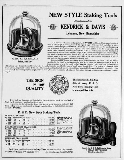
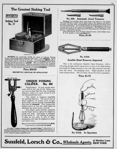
The two catalog pages came from the 1909 Keystone Catalog.
[Be Sure to Click on Any Image to Enlarge It.]
This category exists for watchmakers and hobbyists
You’ve seen tools like the ones in these catalog pages before. They’re often for sale on eBay and tool shops on-line.
The two catalog pages came from the 1909 Keystone Catalog.
[Be Sure to Click on Any Image to Enlarge It.]
Flat and Round Face Solid Punches
| K&D | Marshall | Boley | Star | Bergeon | ||
| Flat Face Solid Punches | 104 | C1 | 13 | |||
| 105 | C2 | 12 | 25 | 233 | ||
| 106 | C3 | 10 | 26 | |||
| 107 | C4 | 9 | 27 | 232 | ||
| 8 | 28 | 231 | ||||
| 108 | C5 | 7 | 29 | 230 | ||
| 109 | C6 | 6 | 31 | 229 | ||
| 110 | C7 | 5 | 32 | 228 | ||
| 111 | C8 | 2.8 | 34 | 225 | ||
| 111A | C9 | 2.7 | ||||
| Round Face Solid Punchs | ||||||
| 112 | D1 | 50 | 36 | 282 | ||
| 113 | D2 | 49 | 37 | |||
| 46.5 | 39 | 281 | ||||
| 114 | D3 | 47 | 38 | |||
| 115 | D4 | 46 | 40 | 280 | ||
| 116 | D5 | 44 | 42 | 275 | ||
| 117 | D6 | 43 | 43 | 276 | ||
| 118 | D7 | 41 | ||||
| 119 | D8 | 39 | 46 | 273 | ||
| 119A | D9 | |||||
If you have spent anytime with staking sets, you know the difficulty of finding compatible ID numbers and what they mean. You will find in this post, a conversion chart for Round Face Hole Punches (Rundpunzen mit Bohrung). See the description below the chart.
| K&D | Marshall | Boley | Star | Bergeon | ||
| Round Face Hole Punches | ||||||
| 74 | B2 | 72 | ||||
| 75 | B3 | 70 | ||||
| 76 | B5 | 68 | 100 | 270 | ||
| 77 | B6 | 67 | ||||
| 78 | B7 | 66 | ||||
| 64 | 101 | |||||
| 79 | B8 | 64 | ||||
| 80 | B9 | 63 | 102 | 267 | ||
| 81 | B10 | 62 | ||||
| 82 | B12 | 61 | 102A | 265 | ||
| 60 | 103 | 264 | ||||
| 83 | B13 | 59 | 103A | 263 | ||
| 84 | B14 | 58 | 104 | 262 | ||
| 85 | B15 | |||||
| 86 | 57.5 | |||||
| 87 | ||||||
| 88 | B16 | 57 | 104A | 260 | ||
| 89 | B17 | 56.5 | ||||
| 89A | 56 | 105 | 258 | |||
| 90 | B18 | |||||
| 91 | 55.5 | |||||
| 92 | B19 | |||||
| 93 | B20 | 55 | 106 | 256 | ||
| 93A | B21 | 54.5 | ||||
| 94 | B22 | |||||
| 95 | B23 | 54 | 107 | 254 | ||
| 96 | B24 | 53.5 | ||||
| 97 | B25 | |||||
| 98 | B26 | 53 | 108 | 252 | ||
| 99 | B27 | 52.5 | ||||
| 100 | B28 | 52 | 109 | 250 | ||
| 101 | B29 | |||||
| 101A | B31 | |||||
| 102 | 51.5 | |||||
| 102A | B32 | |||||
| 103 | B30 | 51 | 110 | 248 | ||
| 103A | B33 | |||||

If you have spent any time with staking sets, you know the difficulty of finding compatible ID numbers and what they mean. You will find in this post, a conversion chart for Flat Face Hole Punches (Flachpunzen, ungebohrt). See the description below the chart.
| K&D | Marshall | Boley | Star | Bergeon | ||
| Flat Face Hole Punches | ||||||
| 43 | 36 | |||||
| 44 | A2 | 35 | ||||
| 45 | A3 | 33 | 65 | 222 | ||
| 46 | A5 | 31 | 66 | 221 | ||
| 47 | A6 | 30 | ||||
| 48 | A7 | 29 | ||||
| 28 | 67 | 219 | ||||
| 49 | A8 | 27 | ||||
| 50 | A9 | 26 | 68 | 217 | ||
| 51 | A10 | 25 | ||||
| 52 | A12 | 24 | 68A | 215 | ||
| 23 | 69 | 214 | ||||
| 53 | A13 | 22 | 69A | 213 | ||
| 54 | A14 | 21 | 70 | 212 | ||
| 55 | A15 | |||||
| 56 | 20.5 | |||||
| 57 | ||||||
| 58 | A16 | 20 | 70A | 211 | ||
| 59 | A17 | 19.5 | ||||
| 59A | 19 | 71 | 210 | |||
| 60 | A18 | |||||
| 61 | 18.5 | |||||
| 62 | A19 | |||||
| 63 | A20 | 18 | 72 | 208 | ||
| 17 | 73 | 206 | ||||
| 63A | A21 | 17.5 | ||||
| 64 | A22 | 16.5 | ||||
| 65 | A23 | |||||
| 66 | A24 | 16 | 74 | 204 | ||
| 67 | A24 | 15.5 | ||||
| 68 | A26 | 15 | 75 | 202 | ||
| 69 | A27 | |||||
| 70 | A28 | |||||
| 71 | A29 | |||||
| 71A | A31 | |||||
| 72 | ||||||
| 72A | A32 | |||||
| 73 | A30 | 14 | 76 | 200 | ||
| 73A | A33 | |||||
For final staking of balance staffs
For final staking of train pinions
For pressing hairspring collets on balance wheels
For use as stumps when inverted into the staking tools. Ideal for riveting “hard” staffs will save wear and tear on the expensive die plate.
When used for final staking of a balance staff or pinion, it is important to select the correct size punch for doing a good job and avoiding damage to the punch. A proper fitting punch should fit freely over the collet hub with a clearance of about .02 to .03 mm. Always tap the punch lightly with a brass hammer turn- ing it about one quarter of a turn after each blow.
If you select too large a punch, it is possible that you may not obtain the full degree of bearing surface, thereby, placing too much pressure on the inside corner of the punch causing it to flatten out or chip. If you select too small a punch, the staff becomes a wedge and will split the punch or round the inside corners of the punch.
I have seen some confusion about a popular tool created by K&D around the turn of the 20th century, e.g., 1902. I notice that confusion as I browse eBay’s listings of pre-owned watch tools. The sellers lack knowledge of the tool, how it works and when K&D made it. Let’s take a shot at clearing-up that confusion, now.
Several watch and jewelry suppliers carried the K&D Sensible Hand Tool Remover. Let’s look at how the largest supplier, Swartchild & Company, advertised the Model 310 in their 1928 catalog like this:
This has a self-acting plunger, which comes down on the top of the hand socket, holding the hands in the tool after they are moved from the watch. Pressure on the dial comes directly over the hour wheel. Does not crack dials. Finely finished. Hard rubber handle.
 |
| Figure 2 |
K&D manufactured the 310 & 310B from 1910 – 1992. The one in the photo below has a Bakelite handle, which would date it in the 1930’s.
Several variations of this tool exists. I have several and each handle is made out of different materials.
The tool came in two models: the 310 and the 310B. The 310 has a larger head on the plunger (see fig 1). When you put the 310 on a wristwatch, it’s simply slips.

The 310B is too small for a pocket watch and it also slips.
Unfortunately, most sellers on eBay put this tool up for auction and have no idea if it’s for a bracelet or a pocket watch.
 |
| Fig 1 |
Another problem exists. In photos the tool appears large. In reality it’s a little large than a tweezers. The photos fool anyone that hasn’t seen a 310.
 |
| Figure 3 |
Note: The tool is much smaller than one would imagine from the photographs we see on eBay and in catalogs. It fits one’s hand nicely.
 |
| Figure 4 |
While we may not know the author, Hammel & Riglander published them.
K&D sold incredible products. They cornered the staking market by 1902. By 1909, the company had many suitors. We can only speculate at this point, but it appears one of those suitors acquired K&D and Hammel & Riglander appears like the winning suitor.
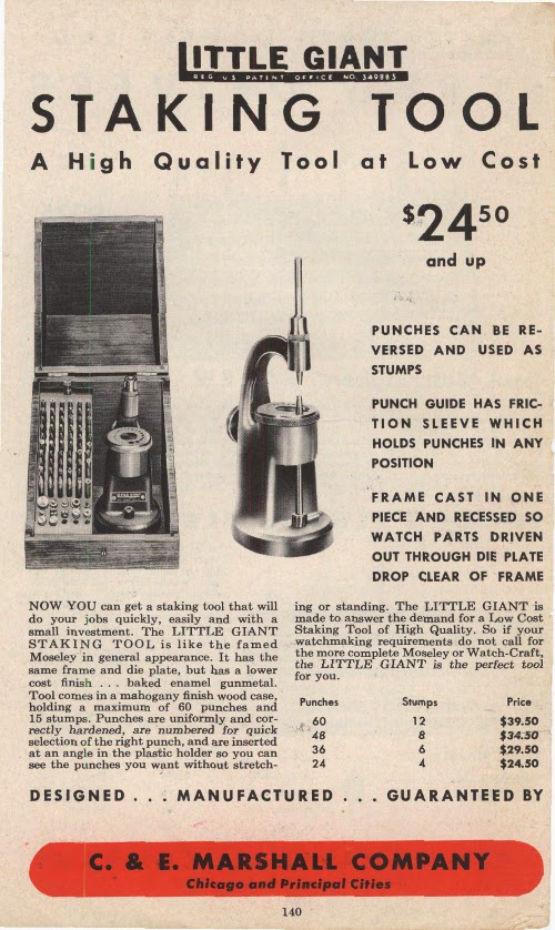
After World War II, C&E Marshall started a price war with Kendrick & Davis, Co. It’s easy to understand, Marshall purchased the Moseley Company and acquired two products: The Lathe and the Moseley Staking Tool. Marshall released a modified version of the K&D 18R. Marshall called their product “The Moseley Staking Tool” and offered it for $63.50 to $87.50. K&D’s set cost $94.
In today’s dollars that doesn’t sound like much difference. I would chose an all tempered steel and heavy chrome plated K&D staking tool to the part steel, part plastic Moseley tool.
Let’s talk in 2014 dollars. In 1946, $63.50 would have the same purchasing power as $618 today. When I stood about three feet tall, my dad used to buy me a Coca Cola for a nickle (5 cents).
In 2014 dollars, a watchmaker could get into a friction jeweling set for $618. The K&D’s friction jeweling set would start at $916. That’s a significant difference.
Let’s look at the product comparison’s. The first figure on the top left is Moseley’s tool. Below it, Figure 3 is the K&D tool. Today, C&E Marshall would have their head handed to them in court. Why? Because, K&D owned the patent. See Figure 5 and the patent date is 1938. That would give K&D the exclusive rights to market their product for nine more years before a competitor could build a similar product. You don’t question the similarities in the designs do you?
Marshall also took K&D head on in the 38mm die plate staking frame. Marshall offered a product comparable to the Model 600 for $24.50 versus K&D’s $42. In 2014 dollars that’s $234 versus $409.
In 2014, you can’t buy either brand new. The K&D 18R Deluxe sells for about $300 on eBay. The Moseley brings about $150.
Why the difference? K&D furnishes several accessories Moseley didn’t even make. K&D included 12 jeweling stakes with handle; two balance staff removers; six jeweling stumps; two adjustable roller removers; several additional “types of” punches; canon pinion tighteners; and cross hole punches to mention a few.
In the 600 Series – Little Giant lines, the C&E Marshall Moseley clone generally sells for more than the K&D set. The two frames are identical with the exception of old plastic in the Moseley tools.
Frankly, I’m stumped.
 |
| Figure2 |
 |
| Figure 1 |
 |
| Figure 3 |
 |
| Figure 4 |
 |
| Figure 5 |
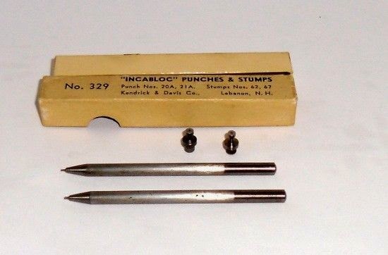
K&D manufactured the the 43-329 Incabloc set specifically to stake Incabloc “Rollers”. The designers of the Incabloc system intended to keep pressure off of the balance pivots and transfer shock to the Incabloc mechanism.
 |
| From 1951 Lindstrom Catalog |
K&D invented their Incabloc staking set to reset the rollers and take the stress off of the pivots of the balance staff after a severe shock. After such an event, jewels tend to move sideways or upwards and the shoulder of the balance staff comes into contact with the setting and stopping it.
If the Incabloc rollers suffer damage, you can remove the roller with the 329 punches while holding the roller in place with the designated stumps.
K&D designed this set for bracelet style watches. Typically, a watchmaker would buy the 329 in addition to to other accessories not included with the 18R Deluxe staking set.
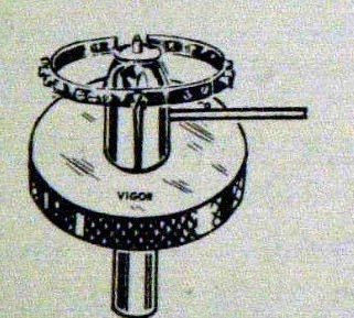
 |
| Hairspring Centering Tool |
These are well-know tools and often difficult to find. Interestingly enough, they are American made. Some of them are over 100 years old.
You may not find contemporary replacements for them, since no one manufacturers them now.
I don’t know that it matters, many of my tools are over 100 years old and work well. I’m not sure the manufacturers expected them to function well for as long as they have, but in those days, planned obsolescence didn’t exist.
What do we have here?
 |
| Duplex Dual Table Removers |
 |
 |
| Adjustible Table Remover |
 |
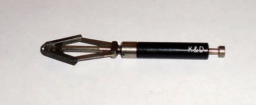
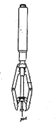
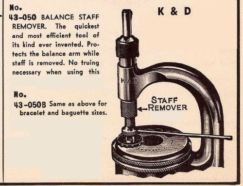
| Staff Remover (Punch) |
The automatic balance staff remover fits in the sleeve of a staking tool. The balance sits on a stump or the die plate itself. A gentle tap on the top of the “punch” will gently push a riveted staff out of its hole without bending the arms or the balance itself. Even so, it is always a good idea to check the balance for poise and truth with calipers.
The K&D 50 balance staff remover is the most popular of all staff removing tools. Here is a brief instruction from K&D’s advertisement:
Select proper hole in your Staking tool dieplate to let the hub of staff through. Place the balance with with staff to be removed in same. Set the remover over the same and insert its punch through the staking tool and main body of remover. Holding the punch in position over pivot with the finger of your right hand tighten the knurled remover nut upwards against staking tool arm. Stop arm of remover will swing against body of Staking Tool and prevent body of tool turning while tightening knurled sleeve. Do not over tighten this sleeve; it is not necessary. Now strike punch a sharp blow with light hammer and staff will come out without injury to Balance; riveting of staff simply being sheared off..
 |
| K&D 50B |
 |
| All together |
Henry B. Fried invented and patented a friction jeweling tool in 1976. The Patent Office awarded him the patent just about the time we began to see a take-over of the watch industry by LED and Quartz movements.
The description and drawing of his patent provides a wealth of information about jeweling, balance and hairspring work. Following is the information:
|
Publication date
|
14 Jun 1977
|
|
Filing date
|
30 Mar 1976
|
|
Priority date
|
30 Mar 1976
|
|
Inventors
|
|
|
Original Assignee
|
|
 |
 |
This post derived its material from the 1910 book, “Staking Tools and How to Use Them”. You’ll find a PDF download link at the bottom.
The material in this post remains relevant today. You will find the writing somewhat archaic.
To view a page, you can click on it and open in another tab.


